
1. Checking the thickness of the lining of the brake pads.
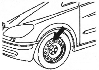
VN 1.015
Note: Front brake outer pad thickness can be checked through the vent holes on the steel rim. The thickness of the inner lining can be checked by accessing the vehicle from below.
Brake pad wear limit: 3.5 mm.
If during the initial check the pad thickness is insufficient, the thickness of all pads should be checked with the removal of the wheels.
1. Removing, checking and installing front brake pads
1.1. Unscrew the cap (1) expansion tank (2).
Before tightening the cap, check the brake fluid level. After the final reduction of the pads, the fluid level may drop.
1.2. Remove the front wheels.
1.3. Disconnect the electrical connector (3) from floating brace (6).
Before installation, check the correct wiring.
1.4. Loosen the bottom screw (2) floating bracket fasteners (6) and turn the bracket up.
Note: When installing the floating bracket, use a new mounting screw.
1.5. Remove the brake pads (10) from bracket (7).
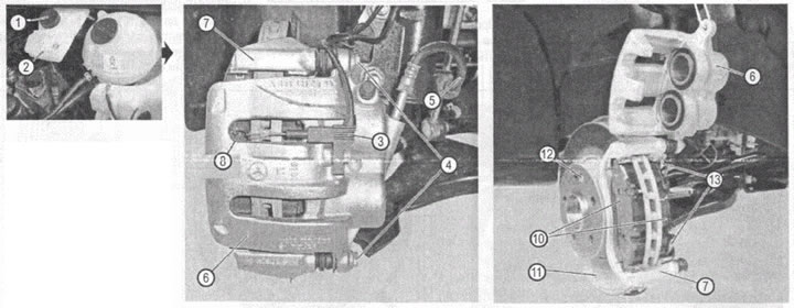
VN 1.016
1. Expansion tank cap.
2. Expansion tank of the brake system.
3. Electrical connector.
4. Screw fastening the floating bracket of the front caliper.
5. Brake tube.
6. Floating caliper bracket.
7. Caliper bracket.
8. Pad wear sensors.
10. Brake pads.
11. Brake disc.
12. Brake disc fixing screw.
13. Bracket mounting screws.
When installing pads with wear sensors, install them so that the sensors are facing outward. Before installing, apply a thin layer of special brake pad paste to the side guide surfaces of the pads.
Checking brake pads and brake discs
1.6. Check the thickness of the brake pads and visually check the condition of the brake discs.
Brake pad wear limit: 3.5 mm.
1.7. Inspect brake hoses for damage (cracks, delaminations, fluid leakage), Replace the brake hoses if they are defective.
1.8. Press the piston of the brake cylinder inward, if the piston sticks when pressed, replace the floating caliper assembly. To remove the bracket, simply unscrew the lower and upper screws securing the bracket to the bracket.
1.9. Remove dirt and scale from the contact surface of the floating bracket with the pads.
1.10. Install in reverse order. Tightening torque of the screw for fastening the floating bracket to the bracket: 30 Nm.
Removing, checking and installing rear brake pads
1.11. Unscrew the cap (1) expansion tank (2).
1.12. Remove rear wheels.
1.13. Disconnect connector (3) pad wear sensor.
1.14. Loosen the screws (4) floating bracket fasteners (6) caliper, remove the floating bracket and move it to the side.
1.15. Remove the brake pads (10) from caliper bracket (7).
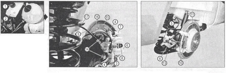
VN 1.017
1. Expansion tank cap
2. Expansion tank of the brake system
3. Electrical connector
4. Screw fastening the floating bracket of the front caliper
5. Brake tube
6. Floating caliper bracket
7. Caliper bracket
8. Pad wear sensors
10. Brake pads
11. Brake disc
13. Rear suspension arm
14. Caliper bracket screws
15. Brake disc protection
16. ABS sensor
17. Rear suspension spring
When installing pads with wear sensors, install them so that the sensors are facing outward. Before installing, apply a thin layer of special brake pad paste to the side guide surfaces of the pads.
Checking brake pads and brake discs
1.16. Check the thickness of the brake pads and visually check the condition of the brake discs.
Brake pad wear limit: 3.5 mm.
1.17. Inspect brake hoses for damage (cracks, delaminations, fluid leakage). In the presence of defects brake hoses should be replaced.
1.18. Press the piston of the brake cylinder inward, if the piston sticks when pressed, replace the floating caliper assembly. To remove the bracket, simply unscrew the lower and upper screws securing the bracket to the bracket.
1.19. Remove dirt and scale from the contact surface of the floating caliper with the pads.
1.20. Install in reverse order. Tightening torque of the screw for fastening the floating bracket to the bracket: 32 Nm.
2. Checking the condition of the brake discs
The disc must be replaced without fail if there are through cracks and burrs more than 0.5 mm deep.
Removal and installation of front brake discs
2.1. Remove the floating calliper caliper assembly and temporarily secure it to the side.
When installing it, the tightening torque of the fastening screws: 172 Nm.
2.2. Loosen the fixing screw (12) brake disc and remove the brake disc (11). It may be difficult to remove and install the brake disc. Therefore, it is allowed to use a light hammer when removing and installing the brake disc.
When installing a drive, use a new fixing screw (12), tightening torque: 22 Nm.
2.3. Clean all contact surfaces, especially the contact surfaces of the brake disc with the hub flange. Even small foreign particles entering between the disc and the hub flange can lead to unacceptable runout of the working surface of the disc.
2.4. Check the condition of the brake disc.
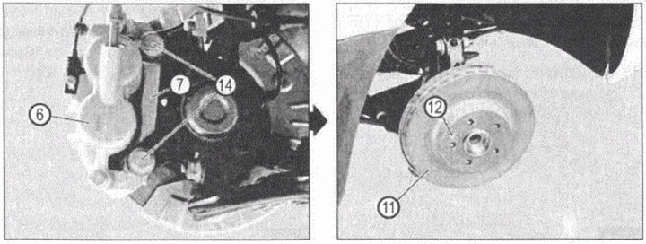
VN 1.018
6. Floating caliper bracket
7. Caliper bracket
11. Brake disc
12.Brake disc fixing screw
14. Caliper bracket screws
Geometric characteristics of the front brake discs
| new disc thickness | 28 mm |
| Minimum allowable thickness | 25 mm |
| Maximum runout of the working surface of the disk | < 0.01 mm |
| Non-flatness of the working surface | <0.04mm |
| Minimum allowable thickness after turning | Grooving is not allowed |
2.6. Install in reverse order.
Removal and installation of rear brake discs
2.7. Remove the floating caliper assembly and secure it aside. When installing it, the tightening torque of the fastening screws: 172 Nm.
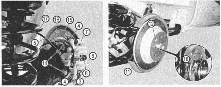
VN 1.019
3. Electrical connector
4. Screw fastening the floating bracket of the front caliper
5. Brake hose
6. Floating caliper bracket
7. Caliper bracket
8. Pad wear sensors
11. Brake disc
12. Brake disc fixing screw
14. Caliper bracket screws
15 Brake disc protection
16. ABS sensor
17. Rear suspension spring
18. Ratchet for adjusting the position of the parking brake pads
2.8. Rotate the brake disc so that you can access (thin screwdriver) to the parking brake shoe adjustment ratchet. By turning the ratchet with a screwdriver, increase the gap between the parking brake pads and the brake disc from the inside (parking brake drum). If you cannot determine which way to turn the ratchet, then determine it empirically: if the ratchet is turned in the wrong direction, then the parking brake pads will block the rotation of the brake disc (parking brake drum). In this case, repeat the operation by turning the ratchet in the opposite direction.
2.9. Block the rotation of the brake disc and unscrew the fixing screw (12).
2.10. Clean all contact surfaces, especially the contact surfaces of the brake disc with the hub flange. Even small foreign particles entering between the disc and the hub flange can lead to unacceptable runout of the working surface of the disc.
2.11. Check the condition of the brake disc.
| Thickness of the new brake disc | 10 mm |
| Minimum Disc Thickness | 8 mm |
| Maximum disc radial runout | 0.15 mm |
| Maximum axial runout of the working surface of the disc | 0.03mm |
| The minimum thickness of the disc after turning the working surface | Disc cutting is not allowed |