
Vehicles with engines 111.948 and 601.970
Disassembly
1. Disassemble the gearbox.
2. Remove bolt 2 (see fig.6.25).
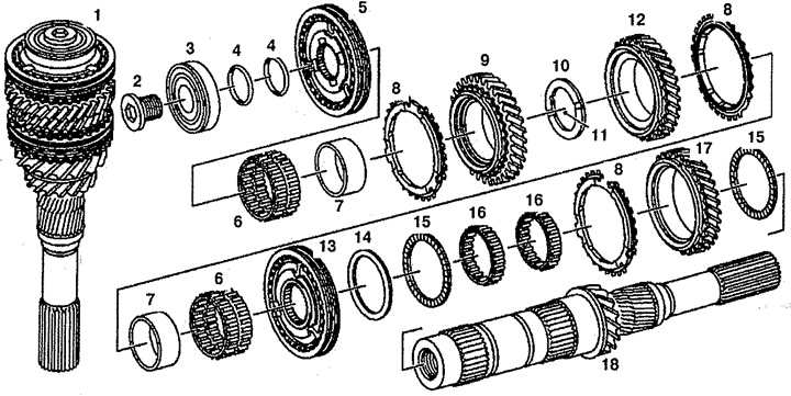
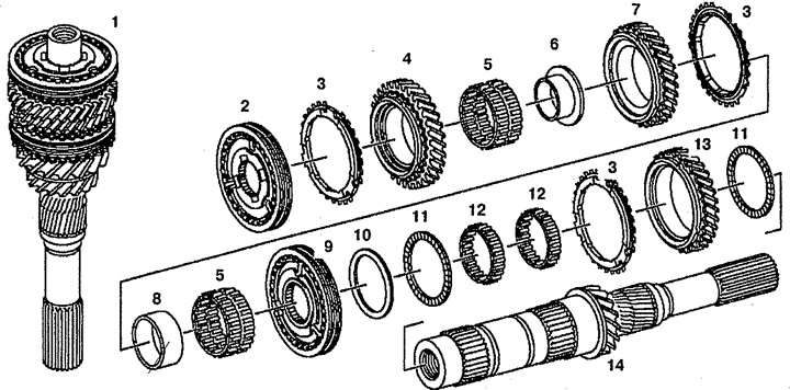
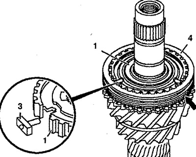
Pic. 6.25. drive shaft (vehicles with engines 111.948 and 601.970):
1. Drive shaft (complete),
2. Bolt,
3, 16. Ball bearing,
4. Gaskets,
5. 5th gear synchronizer clutch,
6. Needle bearing,
7. Bearing sleeve,
8. Synchronizer ring,
9. 5th gear,
10, 14. Retaining gasket,
11. Ball,
12. 4th gear,
13. 3rd and 4th gear synchronizer clutch,
15. Thrust bearing (green/black),
17. Gear 3rd gear,
18. Shaft.
3. Install the plate 19 between the synchronizer ring 8 and the gear wheel 12 (see fig.6.26).
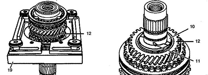
Pic. 6.26. drive shaft (vehicles with engines 111.948 and 601.970):
10. Thrust gasket,
11. Ball,
12. 4th gear,
19. Removable plate.
4. Install the thrust piece, press out the ball bearing 3, 5 and gears 12 and 9. The bushings 7 and the needle bearing 6 of the 4th and 5th gears are the same, but it is not recommended to mix them. Also do not mix gaskets 4 of the drive shaft with the same of the driven shaft.
5. Remove ball 11.
6. Disassemble the clutch 5 of the synchronizer of the 5th gear. To do this, remove the sliding sleeve 5 from the synchronizer body 1 (see fig. 6.27). Remove spring 2 and snap ring 4.
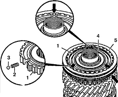
Pic. 6.27. Disassembly and assembly of the 5th gear:
1. Synchronizer housing,
2. Spring,
3. Ball,
4. Retaining ring,
5. Sliding sleeve.
7. Press out bearing sleeve 7, synchronizer sleeve 5 and gear 17.
8. Remove roller 16 and thrust 15 bearings.
9. Disassemble the clutch 13 of the synchronizer for engaging the 3rd and 4th gears, to do this, remove the sliding sleeve 4 from the synchronizer housing 1 (see fig.6.28). Remove spring 2 from synchronizer body 1.
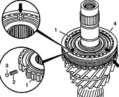
Pic. 6.28. Disassembly and assembly of the 3rd and 4th gear engagement mechanism:
1. Synchronizer housing,
2. Spring,
3. Ball,
4. Sliding sleeve.
10. Check the wear between the synchronizer ring 8 and the 5th gear 9 (see fig.6.29). It should be 0.8 mm. Replace them if necessary.
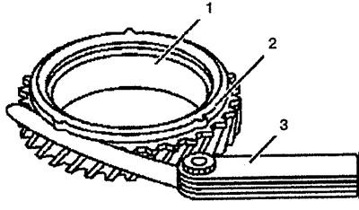
Pic. 6.29. Check for wear between inner synchronizer rings and 5th gear:
1. 5th gear,
2. Synchronizer ring,
3. Probe.
Assembly
eleven. Lubricate all bearings with oil prior to installation.
12. Insert the thrust bearing 15. In the original state, the 2nd gear thrust bearing 15 is black, and the synchronizer sleeve thrust bearing 13 is green. New bearings 15 are green.
13. Insert both roller bearings 16 and gear 17.
14. Insert ring 8 of the synchronizer.
15. Insert thrust bearing 15.
16. Insert the synchronizer sleeve 13 into the synchronizer housing with the larger cuff up and press it in. The guide rings 8 of the synchronizer must engage with the recess of the synchronizer housing. While pressing, lift gear 17 to properly install thrust washer 14 and thrust bearing 15.
17. Install the synchronizer sleeve 13. Press the sliding sleeve 4 onto the synchronizer body 1 and make sure that the groove (arrow) matches 3rd gear (see fig.6.28). Insert springs 2 into synchronizer housing 1. Compress springs 2 and insert balls 3. Insert 4th gear synchronizer ring, push back and set sliding sleeve 4 to neutral position.
18. Insert ring 8 of the synchronizer. The guide rings 8 of the synchronizer must engage with the recess of the synchronizer housing.
19. Press in the bearing bush 7 until it stops and insert the needle bearing 6.
20. Insert gear 12.
21. Insert ball 11 and thrust washer 10.
22. Press the bushing 7 of the bearing up to the stop and insert the needle bearing 6.
23. Install gear 9.
24. Insert ring 8 of the synchronizer.
25. Insert the synchronizer sleeve 5 into the synchronizer housing and press it in with the blocking ring upwards. The guide rings 8 of the synchronizer must engage with the recess of the synchronizer housing.
26. Install the synchronizer sleeve 5. Press the sliding sleeve 5 onto the synchronizer body so that the groove (arrow) matched the 5th gear (see fig.6.27). Insert springs 2 into synchronizer body 1. Compress springs 2 and insert balls 3. Insert synchronizer retaining ring. Set sliding sleeve 4 to neutral position.
27. Install the removed gaskets 4.
28. Press the ball bearing 3 with the groove up.
29. Screw in bolt 2. Lubricate the threaded part of bolt 2 with Loctite 243 adhesive.
30. Assemble the gearbox.
Vehicles with engine 611.980
Disassembly
31. Disassemble the transmission.
32. Disassemble the synchronizer clutch 2 5th gear (see fig.6.30). To do this, remove the retaining ring 4 (see fig.6.31). Press the sliding sleeve 2 through the bottom of the synchronizer body 1. Remove the locking pins 3.
Pic. 6.30. drive shaft (vehicles with engine 611.980):
1. Drive shaft (complete),
2. 5th gear synchronizer clutch,
3. Synchronizer ring,
4. 5th gear,
5. Needle bearing,
6, 8. Bearing sleeve,
7. 4th gear,
9. 3rd and 4th gear synchronizer clutch,
10. Thrust gasket,
11. Thrust bearing,
12. Ball bearing,
13. 3rd gear,
14. Drive shaft.
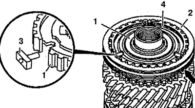
Pic. 6.31. Disassembly and assembly of the 5th gear (vehicles with engine 611.980):
1. Synchronizer housing,
2. Sliding sleeve,
3. Locking pin,
4. Retaining ring.
33. Press out the synchronizer housing using a removable plate 16 (see fig.6.32).
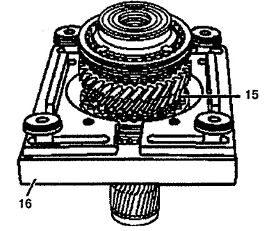
Pic. 6.32. drive shaft (vehicles with engine 611.980):
15. 4th gear,
16. Removable plate.
34. Remove gear wheel 4 of the 5th gear with ring 3 of the synchronizer. Check the wear of the synchronizer ring (see fig.6.29). It should be 0.8 mm.
35. Remove needle bearing 5 and sleeve 6 from drive shaft 14.
36. Disassemble the synchronizer clutch 9 for 3rd and 4th gears. To do this, press the sliding sleeve 2 down from the synchronizer body 1 (see fig.6.33). Remove lock pins 3.
37. Press out the synchronizer ring.
38. Remove the needle bearing 5 and sleeve 8.
39. Remove thrust washer 10 and thrust bearing 11.
40. Remove gear 13 3rd gear with synchronizer ring. Check the wear of the synchronizer ring (see fig.6.29).
41. Remove both roller bearings 12.
42. Remove thrust bearing 11.
Assembly
43. Lubricate all bearings with oil prior to installation.
44. Install thrust bearing 11, both roller bearings 12, 3rd gear gear 13, synchronizer ring 3, thrust bearing 11 and thrust washer 10.
45. Install the synchronizer housing with the larger cuff up and press it in. The guide rings 8 of the synchronizer must engage with the recess of the synchronizer housing.
46. Collect the coupling 9 of the synchronizer of inclusion of the 3rd and 4th gears. To do this, install the sliding sleeve 2 on the synchronizer body 1 with a groove (arrow) up so that it matches the 1st gear (see fig.6.33). Insert locking pins 3 under pressure. Set sliding sleeve 2 to neutral position.
Pic. 6.33. Dismantling and assembly of the mechanism of inclusion of the 3rd and 4th gears (vehicles with engine 611.980):
1. Synchronizer housing,
2. Sliding sleeve,
3. Locking pin,
4. Retaining ring.
47. Install needle bearing 5 and bushing 8 on drive shaft 14.
48. Press the ring 3 of the synchronizer with the sleeve 8 until it stops and insert the needle bearing 5.
49. Install gear 7 4th gear.
50. Press bushing 6 until it stops and insert needle bearing 5.
51. Install gear 4 5th gear.
52. Establish a ring 3 synchronizers.
53. Install the 5th gear synchronizer clutch 2 on the synchronizer housing and press it in so that the groove of the retaining ring is directed upwards.
54. Install 5th gear synchro clutch 2.
55. Assemble the gearbox.