
Vehicles with engines 111.948 and 601.970
Disassembly
1. Disassemble the gearbox.
2. Remove bolt 2 (see fig.6.34).
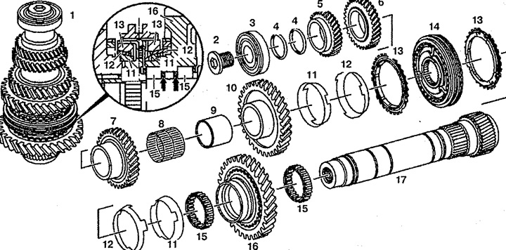
Pic. 6.34. driven shaft (vehicles with engines 111.948 and 601.970):
1. Driven shaft (complete),
2. Bolt,
3. ball bearing,
4. Gaskets,
5. 5th gear,
6. 4th gear,
7. 3rd gear,
8. Needle bearing,
9. Bearing sleeve,
10. Gear 2nd gear,
11. Friction ring,
12. Taper ring,
13. Synchronization ring,
14. Synchronizer clutch for 1st and 2nd gears,
15. Roller bearing,
16. 1st gear,
17. Driven shaft.
3. Press out the ball bearing 3 and gears 5 of the 5th and 6th and 4th gears. Do not mix gaskets 4 with the same drive shaft.
4. Hook the 1st gear on the synchronizer sleeve 14 for engaging 1st and 2nd gears, insert the removable plate between the gear 10 and the bushing.
5. Insert the pressure sleeve, press out the fixed gear 7 3rd gear and gear 10 2nd gear and remove the needle bearing 8.
6. Set the synchronizer clutch 14 to the neutral position.
7. Press out the bearing sleeve 9, the synchronizer sleeve 14 for engaging the 1st and 2nd gears and remove the gear 16 for the 1st gear.
8. Disassemble the clutch 14 of the synchronizer of the inclusion of the 1st and 2nd gears. To do this, remove the sliding sleeve 2 from the synchronizer housing. Loosen balls 5 and locking fingers 4 for a while (see fig.6.35). Remove springs 3.
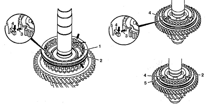
Pic. 6.35. Dismantling and assembly of the clutch of the synchronizer of inclusion
1st and 2nd gears (vehicles with engines 111.948 and 601.970):
1. Synchronizer housing,
2. Sliding sleeve,
3. Spring,
4. Locking pin,
5. Ball.
9. Remove roller bearing 15.
10. Check the wear of the rings 13 of the synchronizer for switching on the 1st and 2nd gears (see fig.6.36). Connect gear 4, wear ring 3, taper ring 2 and timing ring 1. Use feeler gauge 5 to check the distance between timing ring 1 and gear 4. It should be 0.8 mm. If the distance is greater than the allowable, replace the friction ring 3 and, if necessary, the rings 2 and 1.
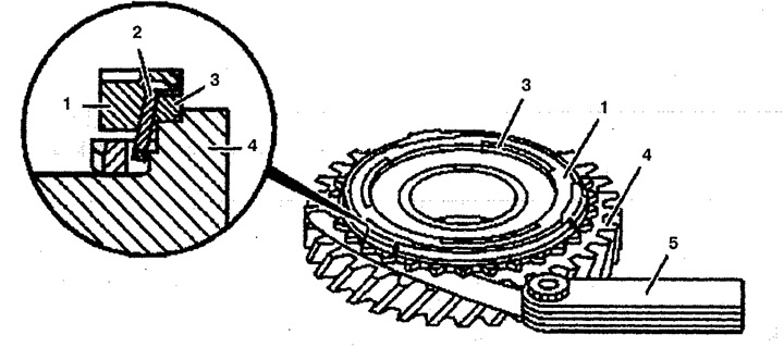
Pic. 6.36. Checking wear between the synchronizer rings and the clutch housing (vehicles with engines 111.948 and 601.970):
1. Synchronization ring,
2. Taper ring,
3. Friction ring,
4. Gear,
5. Probe.
11. Check the driven shaft 17 and the holes for fixing gears 5, 6 and 7 for wear.
Assembly
12. Lubricate all bearings with oil prior to installation.
13. Install roller bearing 15, 1st gear 16, roller bearing 15, friction ring 11, taper ring 12, and timing ring 13.
14. Install the synchronizer sleeve 14 on the synchronizer housing with the grooves upwards and press it in. The guides on the synchronization ring 13 must be engaged with the synchronizer body.
15. Collect the coupling 14 of the synchronizer of inclusion of 1st and 2nd transfers. Press the sliding sleeve 2 onto the synchronizer body and make sure that the groove (arrow) matches the 1st gear. Notched teeth (arrow) must be installed in the center of the recess of the synchronizer housing 1 (see fig.6.35). Insert springs 3 and locking pins 4 into the recess in the synchronizer body 1. The chamfer of the locking pin 4 must be directed outward. notches (arrow) on the extended part of the locking pin 4 must be visible. Raise the locking pins 4 so that the balls 5 can be inserted into the holes. Press the balls 5 into the holes, set the locking pins 4 down and after a while insert them into the sliding sleeve 2. Insert the 2nd gear timing ring, press it in and set the sliding sleeve 2 to the neutral position.
16. Install the timing ring 13, cone ring 12, friction ring 11. The guides of the friction ring 11 must be engaged with the timing ring 13.
17. Press in the bearing sleeve 9 until it stops.
18. Install needle bearing 8 and pinion 10 2nd gear. Taper ring guides 12 should engage with gear grooves 10.
19. Press in the gear wheel 7 of the 3rd gear with the grooves up to the stop.
20. Press the gear wheel 6 of the 4th gear with the grooves up until it stops.
21. Install gaskets 4.
22. Press in the ball bearing 3 with the groove up.
23. Screw in bolt 2.
24. Assemble the gearbox.
Vehicles with engine 611.980
Disassembly
25. Disassemble the gearbox.
26. Press out the fixed gears 2 and 3 of the 5th and 4th gears (see fig.6.37).
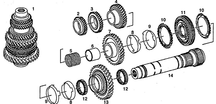
Pic. 6.37. driven shaft (vehicles with engine 611.980):
1. Driven shaft (complete),
2. 5th gear,
3. 4th gear,
4. 3rd gear,
5. Needle bearing,
6. Bearing sleeve,
7. Gear 2nd gear,
8. Friction ring,
9. Taper ring,
10. Synchronization ring,
11. Synchronizer clutch for 1st and 2nd gears,
12. Roller bearing,
13. 1st gear,
14. Driven shaft.
27. Engage first gear.
28. Press fixed gears 4 and 7 for 3rd and 2nd gears.
29. Disconnect the needle bearing 5 and the bearing bush 6.
30. Press out the clutch 11 of the synchronizer for switching on the 1st and 2nd gears.
31. Disassemble the P synchronizer clutch. Check the wear of the synchronizer rings (see fig.6.36).
32. Remove roller bearing 12.
33. Check the driven shaft 14 and the holes for fixing gears 2, 3 and 4 for wear.
34. Lubricate all bearings with oil prior to installation.
35. Install roller bearing 12, gear 13, friction ring 8, timing ring 10.
36. Install the clutch 11 on the synchronizer housing with the grooves up and press it in.
37. Assemble the clutch 11 for 1st and 2nd gears (see fig.6.35).
38. Install timing ring 10, taper ring 9, friction ring 8.
39. Press in the bearing sleeve 6 until it stops.
40. Install needle bearing 5 and gear 7.
41. Press the gear with 4 grooves up until it stops.
42. Press the gear with 3 grooves up until it stops.
43. Press the gear with 2 grooves up until it stops.
44. Assemble the gearbox.