
Cars BMW Cars Volkswagen Cars Chevrolet Cars Land Rover Cars Lada Cars Honda Cars Peugeot
English Русский
Български
Беларускі
Український
Српски
Hrvatski
Română
Polski
Slovenský
Magyar
Bookmark News and articles Sitemap Feedback Site search
MercedesMan.ru


A-Class C-Class E-Class G-Class M-Class S-Class Others
190 (W201) (1982-1993) W202 (1993-2000) W203 (2000-2007)
  • Main
  • C-Class
  • W201 (1982-1993)
  • Chassis
  • Car suspension
  • Front steering knuckle — removal and installation

Front steering knuckle — removal and installation (Mercedes-Benz C-Class W201)

0
Contents: Removal ↡ Installation ↡
Note: When installing, you will need new lower bolts and a nut for the upper shock absorber mounting bolt to the knuckle, a nut for the ball joint of the steering rod and a nut for the clamp of the ball joint of the lower arm.


Removal


1. Apply the parking brake, then raise the front of the vehicle with a jack and securely support it on stands (see "Lifting the car with a jack and placing it on supports"). Remove the corresponding wheel.

2. If the steering knuckle is being replaced, remove the hub as described in paragraph 3.

3. If the steering knuckle is to be used, loosen and remove the two bolts securing the caliper support bracket to the knuckle, then slide the caliper off the rotor. Note: Discard the caliper bolts as new ones must be used for installation. Use a piece of string or wire to tie the caliper to the suspension spring to prevent stretching of the brake hoses. On ABS models, also remove the wheel sensor as described in Chapter 9.

4. Loosen and unscrew the nut securing the ball joint to the steering knuckle (see fig. 4.4) and press out the conical pin using a universal ball joint puller.
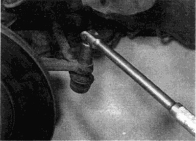
Fig. 4.4. Unscrew the mounting nut and separate the steering rod from the steering knuckle

Fig. 4.4. Unscrew the mounting nut and separate the steering rod from the steering knuckle


5. When performing work on the right fist on models equipped with the ASD system (automatic differential lock), unscrew the mounting bolts and remove the wheel acceleration sensor.


Warning: The ASD sensor is shock sensitive and should not be dropped or hit.


6. Once the knuckle is removed, the lower control arm needs to be supported. Do this by placing a jack and a block of wood under the arm and lifting it up. Alternatively, you can compress the spring with a spring compressor.

7. Loosen and remove the two lower bolts securing the strut to the shock absorber.

8. Loosen and remove the nut and washer, then remove the upper bolt securing the shock absorber to the steering knuckle.

9. Separate the steering knuckle from the shock absorber, then loosen and remove the lower arm ball joint pinch bolt and nut (see fig. 4.9).
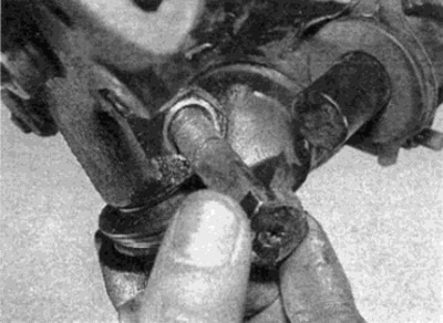
Fig. 4.9. Remove the lower arm ball joint tie bolt and nut

Fig. 4.9. Remove the lower arm ball joint tie bolt and nut


10. Separate the knuckle from the lower arm ball joint and remove it from the vehicle (see fig. 4.10). Inspect the fist; if any wear or damage is found, replace it. Note that the tie rod can be replaced separately. The tie rod ends should be replaced each time they are loosened.
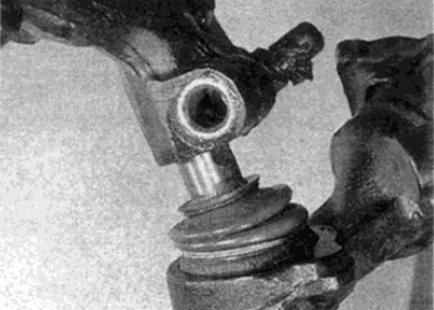
Fig. 4.10. Separate the steering knuckle from the lower arm ball joint

Fig. 4.10. Separate the steering knuckle from the lower arm ball joint


Installation


11. Before installing the lever, clean the threads of the lower bolt holes using a tap of the appropriate size.

Tip: If you don't have the required tap, go through the threads using an old bolt with a split groove on the thread.


12. Align the knuckle with the ball joint pin. Insert the clamp bolt, then install a new nut and tighten it to the required torque. To protect the unit from corrosion, place sealant in the clamp cut.

13. Place the knuckle onto the shock absorber, making sure that the protrusion on the knuckle matches the hole.

14. Install the upper knuckle bolt and washers, then install the new nut. Install the two new lower shock absorber-to-knuckle bolts. Once all the bolts are in place, push the knuckle shaft down firmly to connect the top of the knuckle to the shock absorber. Hold the knuckle in this position and tighten the upper bolt nut to the specified torque. Then tighten both lower bolts.

15. Remove the jack/spring compressor (depends on what you used) and connect the ball joint of the steering rod to the steering knuckle. Install a new nut on the ball joint and tighten it to the required torque.

16. Install the hub as described in paragraph 3.

17. On models where the hub has not been removed, remove all traces of the locking compound (see item 11) and slide the caliper into place on the disc. Install new mounting bolts and tighten them to the required torque (see Chapter 9). Where provided, install the ASD sensor to the hub and tighten the mounting bolts securely.

19. Install the wheel, then lower the vehicle to the ground and tighten the wheel bolts to the required torque.
This article is available at: russian, bulgarian, belarusian, ukrainian, serbian, croatian, romanian, polish, slovak, hungarian
The article has been verified: Lukyanov Nikita Ilyich
Share with friends:
◀ Previous
C-Class 190 (W201) / Car suspension
Next ▶

Front hub — removal, disassembly and installation
Front Hub Bearing — Checking and Adjusting
Basic information
Technical data
Front suspension shock absorbers — removal, disassembly and installation
Front suspension spring — removal and installation
Lower control arm of the front suspension — removal, disassembly and installation
Front suspension anti-roll bar — removal and installation
Rear Hub Holder — Removal and Installation
More similar articles for repairing other models

☛ Adjusting the position of the steering wheel Mercedes W168 (1997-2004)
☛ Removal, disassembly and installation of the steering knuckle Mercedes W123 (1976-1985)
☛ Checking the condition of suspension and steering components Mercedes W463 (1999-2019)
☛ Removal and installation of steering knuckle, replacement of ball… Mercedes W163 (1997-2005)
☛ Front steering knuckle — removal and installation Mercedes W220 (1998-2005)
☛ Front control arm and steering knuckle Mercedes Vito 2 (2003-2014, diesel)
Link in different formats to this article
Comments and feedback from visitors
No comments yet


How much will 49 + 18 ?


W203 (2000-2007) 
  • General information
  • Introduction to guide
  • User manual
  • Maintenance
  • Power unit
  • Gasoline engines
  • Diesel engines
  • Cooling system
  • Ventilation and heating
  • Supply system
  • Injection system (gasoline)
  • Injection system (diesel)
  • Exhaust system
  • Ignition and control system
  • Charge and launch systems
  • Transmission
  • Mechanical gearbox
  • Automatic gearbox
  • Clutch and drive shafts
  • Differential
  • Chassis
  • Brake system
  • Car suspension
  • Steering
  • Body
  • Exterior (external elements)
  • Interior (internal elements)
  • Electrical equipment
  • Equipment and devices
  • Lighting system
  • Electrical diagrams (2000)
  • Electrical diagrams (since 2001)
W202 (1993-2000) 
  • General information
  • User manual
  • Driving a car
  • Car care
  • Maintenance
  • Power unit
  • Gasoline engines
  • Diesel engines
  • Lubrication system
  • Cooling system
  • Heating and ventilation
  • Ignition system
  • Fuel system
  • Injection system (gasoline)
  • Injection system (diesel)
  • Exhaust system
  • Transmission
  • Clutch
  • Car gearbox
  • Chassis
  • Suspension, wheels and tires
  • Steering
  • Brake system
  • Body
  • Exterior (external elements)
  • Interior (internal elements)
  • Doors and windows
  • Electrical equipment
  • Equipment and devices
  • Power devices
  • Lighting system
  • Electrical circuits
190 (W201) (1982-1993) 
  • General information
  • Introduction to the guide
  • Operation and care
  • Maintenance (gasoline)
  • Maintenance (diesel)
  • Troubleshooting
  • Power unit
  • Petrol engine I4
  • Petrol engine V6
  • Diesel engines
  • Engine overhaul
  • Cooling and heating
  • Power system (carburetor)
  • Injection system (gasoline)
  • Injection system (diesel)
  • Exhaust system
  • Charge and start system
  • Ignition system (I4)
  • Ignition system (V6)
  • Diesel heating system
  • Transmission
  • Clutch
  • Mechanical gearbox
  • Automatic gearbox
  • Cardan shaft and axle shafts
  • Chassis
  • Brake system
  • Car suspension
  • Steering
  • Body
  • Exterior (external elements)
  • Interior (internal elements)
  • Doors, locks and windows
  • Electrical equipment
  • Equipment and devices
  • Electrical circuits
 
MercedesMan.ru © 2017–2026 · Mobile version · Read about Mercedes · Sitemap: EN BG BY UA RS HR RO PL SK HU · Feedback · Site search · Bookmark A-Class (W168) · C-Class (W201) · C-Class (W202) · C-Class (W203) · E-Class (W123) · E-Class (W124) · E-Class (W210) · G-Class (W463) · M-Class (W163) · S-Class (W116, petrol) · S-Class (W126, petrol) · S-Class (W140) · S-Class (W220) · Sprinter · Vito 1 · Vito 2 · Vario 814D ·
 
We only use cookies without which some of the site's features may not be available.