
Note: New axle bolt nuts will be required for installation. On the bottom bar (transverse) you will also need a new ball joint nut.
Removing
Note: If more than one adjustment rod is being removed at the same time, support the lower arm with a jack and block of wood.
1. Place wedges under the front wheels, then jack up the rear of the vehicle and support it securely on jack stands (see "Jacking up the car and placing it on stands"). Remove the relevant wheel.
Upper camber control bar
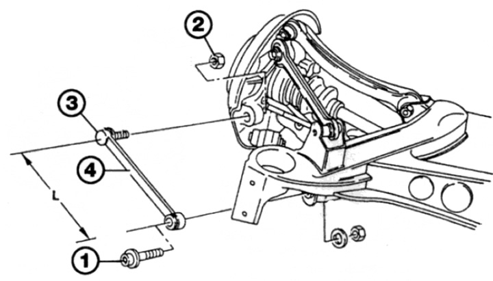
2. Loosen and remove the nut and pull out the axial bot attaching the rod to the hub holder (see fig. 13.2).
Pic. 13.2. Upper camber bar attachments
3. Loosen and remove the nut and pivot pin securing the bar to the subframe. Remove the bar from the vehicle. If necessary, knock out the metal bushing from the rubber bushing of the hub holder.
4. Inspect the stem, paying particular attention to the rubber bushings. If bushings or axle bolts are worn, replace parts.
Upper diagonal bar
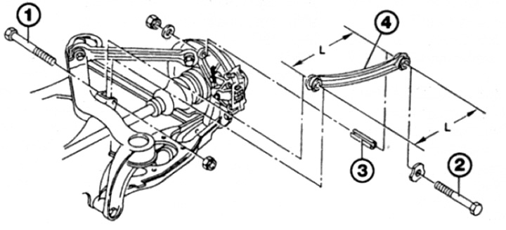
5. Remove the boom as described in paragraphs. 2 by 4 skipping notes about the metal sleeve (see fig. 13.5).
Pic. 13.5. Mounting of the upper diagonal rod
1 Internal axle bolt
2 Outer axle bolt
3 Bar
L = 247 + 0.3 mm
Lower longitudinal push rod
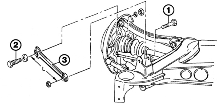
6. Remove the boom as described in paragraphs. 2 by 4 (see fig. 13.6).
Pic. 13.6. Fastening of the lower longitudinal push rod
Lower cross bar
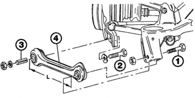
7. Before removal, apply alignment marks between the inner rod bolt, eccentric washers and subframe. It's necessary. to ensure that the adjustment of the rear wheel toe-in remains unchanged during installation (see fig. 13.7).
Pic. 13.7. Lower cross bar attachments
1 Internal axle bolt
2 External fastening nut
3 Outer axle bolt
4 Bar
L = 245 + 0.5 mm
8. Loosen and remove the nut and eccentric washer and remove the axle bolt securing the rod to the subframe.
9. Turn away a nut from a finger of the spherical joint, then separate the joint from the holder of a nave and remove a bar from the car. If necessary, use a ball joint puller.
10. Check the support bushings for damage and make sure that the hinge moves without binding and the boot is not damaged. If necessary, replace the stem.
Installation
Upper camber control bar
11. Where necessary, hammer the metal bushing into place into the rubber bushing of the hub holder.
12. Put the rod in place and insert the axle bolts. Install new nuts on the bolts and, at this stage, tighten them by hand.
13. Install the rear wheel, then lower the vehicle to the ground and tighten the wheel bolts to specification.
14. With the vehicle on the ground, rock the vehicle until the bar is in the desired position, then tighten the axle bolt nuts to the required torque.
Upper diagonal bar
15. Install the boom as described in paragraphs. 11-14.
Lower longitudinal push rod
16. Install the boom as described in paragraphs. 11-14.
Lower cross bar
17. Maneuver the stem back into place, then insert the axle inner bolt, eccentric washer and install the new mounting nut. Align the marks made before removal and lightly tighten the nut.
18. Establish a new fastening nut on a finger of the spherical hinge and tighten it with demanded effort.
19. Install the rear wheel, then lower the vehicle to the ground and tighten the wheel bolts to the correct torque.
20. With the vehicle on the ground, rock the vehicle until the boom is in the correct position. Make sure that the marks on the subframe, eccentric washers and axle bolt have not shifted. After that, tighten the nuts of the axle bolts with the required force.
Note: It is recommended that the rear wheel alignment be checked by a workshop as soon as possible.