
Cars BMW Cars Volkswagen Cars Chevrolet Cars Land Rover Cars Lada Cars Honda Cars Peugeot
English Русский
Български
Беларускі
Український
Српски
Hrvatski
Română
Polski
Slovenský
Magyar
Bookmark News and articles Sitemap Feedback Site search
MercedesMan.ru


A-Class C-Class E-Class G-Class M-Class S-Class Others
190 (W201) (1982-1993) W202 (1993-2000) W203 (2000-2007)
  • Main
  • C-Class
  • W201 (1982-1993)
  • Chassis
  • Car suspension
  • Rear shock absorber — removal, inspection and installation

Rear shock absorber — removal, inspection and installation (Mercedes-Benz C-Class W201)

0
Contents: Removal ↡ Examination ↡ Installation ↡
Note: This operation is not performed on models equipped with adjustable rear suspension.


Warning: A new lower shock absorber bolt nut will be required during installation.


Removal


2. Place chocks under the front wheels, then jack up the rear of the vehicle and secure it on stands (see "Lifting the car with a jack and placing it on supports"). To improve access, remove the corresponding wheel.

3. Remove the mounting screws and the protective cover from the base of the lower control arm. Place a jack and a block of wood under the lower control arm and raise the jack to support the weight of the arm (see Fig. 11.3, a, b).
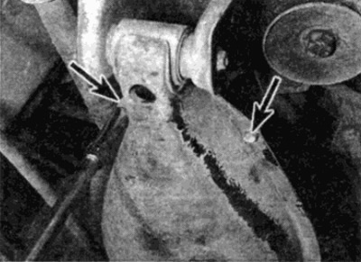
Fig. 11.3, a. Unscrew the fastening screws (shown by arrows)...
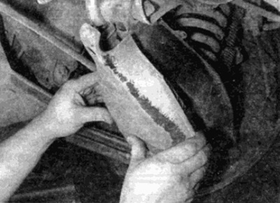
Fig. 11.3, a. Unscrew the fastening screws (shown by arrows)...


Fig. 11.3, b....and remove the protective cover from the base of the lower arm

Fig. 11.3, b....and remove the protective cover from the base of the lower arm


4. Remove the trim on the side of the luggage compartment to access the upper shock absorber support (see Fig. 11.4, a, b).
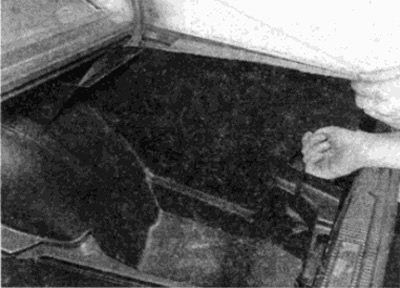


Fig. 11.4, a. Remove the trim on the side of the luggage compartment...
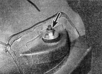
Fig. 11.4, a. Remove the trim on the side of the luggage compartment...


Fig. 11.4, b....to get to the upper support of the rear shock absorber (shown by arrow)

Fig. 11.4, b....to get to the upper support of the rear shock absorber (shown by arrow)


5. Using an open-end wrench, hold the upper shock absorber mount nut and loosen and remove the lock nut. Unscrew the upper shock absorber mount nut, taking care not to turn the shock absorber body/piston, and remove the washer and rubber bushing (see Fig. 11.5, a-c).
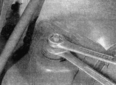
Fig. 11.5, a. Unscrew the two nuts...
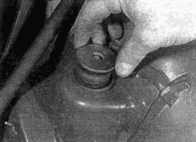
Fig. 11.5, a. Unscrew the two nuts...


Fig. 11.5, b.... remove the washer
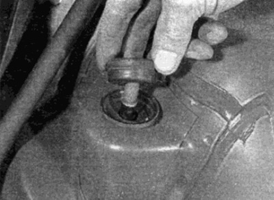
Fig. 11.5, b.... remove the washer


Fig. 11.5. c....and then the rubber bushing

Fig. 11.5. c....and then the rubber bushing


Warning: Do not attempt to remove the upper shock absorber mount nut while the lower arm is supported by a jack.


6. Working from underneath the vehicle, loosen and remove the lower mount bolt nut and remove the bolt and washers (see fig. 11.6).
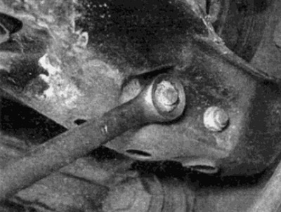
Fig. 11.6. Unscrew the nut and remove the bolt of the lower shock absorber support

Fig. 11.6. Unscrew the nut and remove the bolt of the lower shock absorber support


7. Carefully lower the suspension arm slightly, then maneuver the shock absorber out from under the wheel arch and remove the rubber bushing from its upper end. On later models (december 1986) also remove the metal bushing that fits onto the upper rubber support bushing, then remove the mudguard from the shock absorber and slide the piston rod buffer off (see Fig. 11.7. a, b).
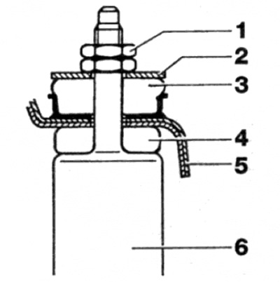
Fig. 11.7. a. Rear shock absorber upper mount parts - early models

Fig. 11.7. a. Rear shock absorber upper mount parts - early models
1 Locknut and support nut
2 Washer
3 Rubber bushing
4 Rubber bushing
5 Body
6 Shock absorber
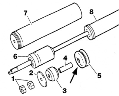

Fig. 11.7, b. Rear shock absorber upper support parts - late models

Fig. 11.7, b. Rear shock absorber upper support parts - late models
1 Locknut and support nut
2 Washer
3 Rubber bushing
4 Metal bushing
5 Rubber bushing
6 Rod buffer
7 Mudguard cover
8 Shock absorber


Examination


8. Check for leaks in the shock absorber. Check for pitting on the piston and damage to the housing. Holding the shock absorber vertically, check the piston movement throughout its entire stroke and then at short movements of 50 to 100 mm. In both cases, a smooth and continuous resistance should be felt. If the resistance is jerky or uneven, or there are signs of wear or damage to the shock absorber, it must be replaced. Check all other parts. If damage or damage is found, replace.

[Text republished from the website Mercedesman.ru]

Installation


9. On later models, slide the stopper onto the shock absorber piston, then install the mud boot and metal bushing.

10. On all models, install the lower shock absorber bushing and reinstall the shock absorber.

11. Align the lower end of the shock absorber with the suspension arm and insert the support bolt. Install the new nut, but do not tighten it too much.

12. Raise the lower suspension arm, checking that the upper end of the shock absorber is correctly positioned in the body.

13. Working from inside the luggage compartment, fit the upper mount bushing and washer to the shock absorber, then thread on the mount nut. Check that the rubber bushing is correctly positioned, then tighten the nut to the specified torque, without allowing the shock absorber body/piston to turn. Hold the mount nut still, fit and tighten the lock nut to the specified torque.

14. Install the decorative panel in the trunk.

15. Install the wheel and lower the vehicle to the ground. Tighten the wheel mounting bolts to the required torque.

16. When the car is on the ground, rock it so that the shock absorber takes the required position, then tighten the nut of the lower support bolt with the required force. Stop the protective cover on the lower arm and tighten the screws of its fastening.
This article is available at: russian, bulgarian, belarusian, ukrainian, serbian, croatian, romanian, polish, slovak, hungarian
The article has been verified: Lukyanov Nikita Ilyich
Share with friends:
◀ Previous
C-Class 190 (W201) / Car suspension
Next ▶

Rear Hub Bearing — Replacement
Rear Hub Holder — Removal and Installation
Front suspension anti-roll bar — removal and installation
Lower control arm of the front suspension — removal, disassembly and installation
Front suspension spring — removal and installation
Rear suspension spring — removal and installation
Rear suspension rods — removal and installation
Lower arm of the rear suspension — removal, disassembly and installation
Rear suspension anti-roll bar — removal and installation
Rear anti-roll bar connecting link — removal and installation
More similar articles for repairing other models

☛ Rear shock absorber — removal and installation Mercedes W168 (1997-2004)
☛ Rear shock absorber — removal and installation Mercedes W124 (1984-1995)
☛ Removal, checking and installation rear shock absorbers Mercedes W463 (1999-2019)
☛ Removal and installation the end cover, replacing the rear crankshaft… Mercedes W163 (1997-2005)
☛ Removal and installation the rear shock absorber strut Mercedes W140 (1991-1998)
☛ Removal and installation the rear shock absorber Mercedes Vito 2 (2003-2014, diesel)
Link in different formats to this article
Comments and feedback from visitors
No comments yet


How much will 36 + 29 ?


W203 (2000-2007) 
  • General information
  • Introduction to guide
  • User manual
  • Maintenance
  • Power unit
  • Gasoline engines
  • Diesel engines
  • Cooling system
  • Ventilation and heating
  • Supply system
  • Injection system (gasoline)
  • Injection system (diesel)
  • Exhaust system
  • Ignition and control system
  • Charge and launch systems
  • Transmission
  • Mechanical gearbox
  • Automatic gearbox
  • Clutch and drive shafts
  • Differential
  • Chassis
  • Brake system
  • Car suspension
  • Steering
  • Body
  • Exterior (external elements)
  • Interior (internal elements)
  • Electrical equipment
  • Equipment and devices
  • Lighting system
  • Electrical diagrams (2000)
  • Electrical diagrams (since 2001)
W202 (1993-2000) 
  • General information
  • User manual
  • Driving a car
  • Car care
  • Maintenance
  • Power unit
  • Gasoline engines
  • Diesel engines
  • Lubrication system
  • Cooling system
  • Heating and ventilation
  • Ignition system
  • Fuel system
  • Injection system (gasoline)
  • Injection system (diesel)
  • Exhaust system
  • Transmission
  • Clutch
  • Car gearbox
  • Chassis
  • Suspension, wheels and tires
  • Steering
  • Brake system
  • Body
  • Exterior (external elements)
  • Interior (internal elements)
  • Doors and windows
  • Electrical equipment
  • Equipment and devices
  • Power devices
  • Lighting system
  • Electrical circuits
190 (W201) (1982-1993) 
  • General information
  • Introduction to the guide
  • Operation and care
  • Maintenance (gasoline)
  • Maintenance (diesel)
  • Troubleshooting
  • Power unit
  • Petrol engine I4
  • Petrol engine V6
  • Diesel engines
  • Engine overhaul
  • Cooling and heating
  • Power system (carburetor)
  • Injection system (gasoline)
  • Injection system (diesel)
  • Exhaust system
  • Charge and start system
  • Ignition system (I4)
  • Ignition system (V6)
  • Diesel heating system
  • Transmission
  • Clutch
  • Mechanical gearbox
  • Automatic gearbox
  • Cardan shaft and axle shafts
  • Chassis
  • Brake system
  • Car suspension
  • Steering
  • Body
  • Exterior (external elements)
  • Interior (internal elements)
  • Doors, locks and windows
  • Electrical equipment
  • Equipment and devices
  • Electrical circuits
 
MercedesMan.ru © 2017–2026 · Mobile version · Read about Mercedes · Sitemap: EN BG BY UA RS HR RO PL SK HU · Feedback · Site search · Bookmark A-Class (W168) · C-Class (W201) · C-Class (W202) · C-Class (W203) · E-Class (W123) · E-Class (W124) · E-Class (W210) · G-Class (W463) · M-Class (W163) · S-Class (W116, petrol) · S-Class (W126, petrol) · S-Class (W140) · S-Class (W220) · Sprinter · Vito 1 · Vito 2 · Vario 814D ·
 
We only use cookies without which some of the site's features may not be available.