
Electro-hydraulic control unit (vehicles with engines 111.601 and 611.980)
Removing
1. Set the selector lever to position "R".
2. Disconnect the negative cable from the battery.
3. Remove the automatic transmission pan.
4. Disconnect connector X106 (see fig.6.59).
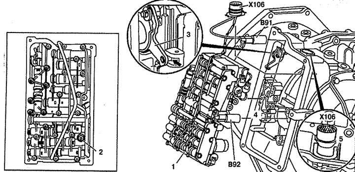
Pic. 6.59. Electro-hydraulic control unit (vehicles with engines 111, 601 and 611.980):
1. Electro-hydraulic control unit,
2. Bolt,
3. gear lever,
4. Sealing sleeves,
5. Retainer,
B91. Inductive output shaft speed sensor,
B92. Inductive GTR turbine speed sensor,
X106. Wiring connector.
5. Remove clamp 5 from connector X106.
6. Remove the B92 inductive sensor. If the electro-hydraulic unit 1 or the B92 inductive sensor is not to be replaced, the X106 connector does not need to be disconnected.
7. Remove bolts 2.
8. Remove the electro-hydraulic unit 1 and after a while disconnect connector X106.
9. Remove inductive sensor B91 and electro-hydraulic unit 1.
10. Remove sealing sleeves 4.
Installation
11. Installation is made in an order, the return to removal. Replace sealing sleeves 4.
Electro-hydraulic control unit (vehicles with engine 104.900)
Removing
1. Remove tray 1 (see fig. 6.60).
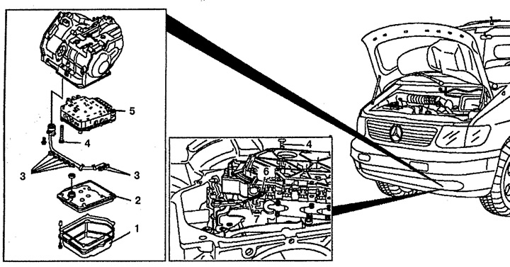
Pic. 6.60. Electro-hydraulic control unit (vehicles with engine 104.900):
1. pallet,
2. Oil filter,
3. Adapter,
4. Bolt,
5. Electro-hydraulic control unit,
6. Slider,
7. Drive rod.
2. Remove oil filter 2.
3. Disconnect sockets 3 conductings.
4. Unscrew the bolts 4 fastening the electro-hydraulic unit 5 and remove it. Disconnect the slider 6 from the drive rod 7.
Installation
5. Installation is made in an order, the return to removal.