
Removal and installation of automatic transmission (vehicles with engines 111.948)
Removing
1. Disconnect the negative cable from the battery.
2. Drain the fluid from the automatic transmission.
3. Drain the coolant.
4. Disconnect the branch pipe 3 of the cooling system from the tube 1 (see fig. 6.47a, 6.476).
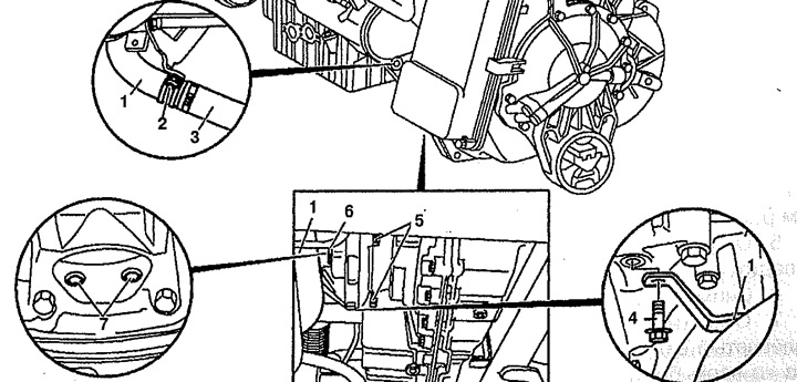
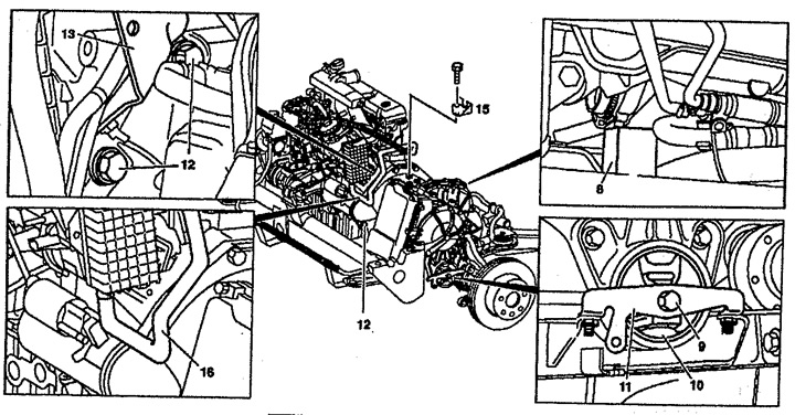
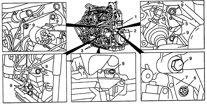
Pic. 6.47a. Removal and installation of automatic transmission (vehicles with engines 111.948):
1. Cooling system tube,
2, 4, 5, 7. Bolt,
3. Pipe of the cooling system,
6. Lid.
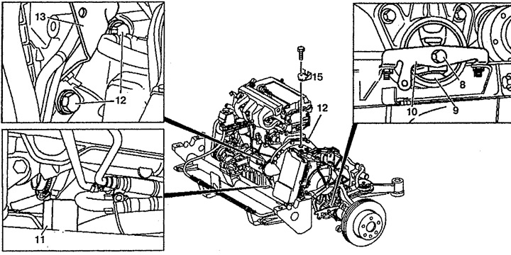
Pic. 6.47 b. Removal and installation of automatic transmission (vehicles with engines 111.948):
8, 12. Bolt,
9. Gearbox support,
10. Bridge,
11. Block,
13. Bracket,
15. Thrust bearing.
5. Turn off bolts 2 and 4, then take a tube 1 aside.
6. Remove cover 6 of the pallet.
7. Remove bolts 7. Rotate crankshaft to access all bolts 7. Rotate crankshaft only 120°in direction of rotation.
8. Remove bolts 5.
9. Remove the subframe with the engine.
10. Remove the intermediate shaft.
11. Disconnect the left axle shaft from the flange.
12. Using the lift 14, lift the gearbox with the engine until the gearbox supports 9 are completely unloaded (see fig.6.48).
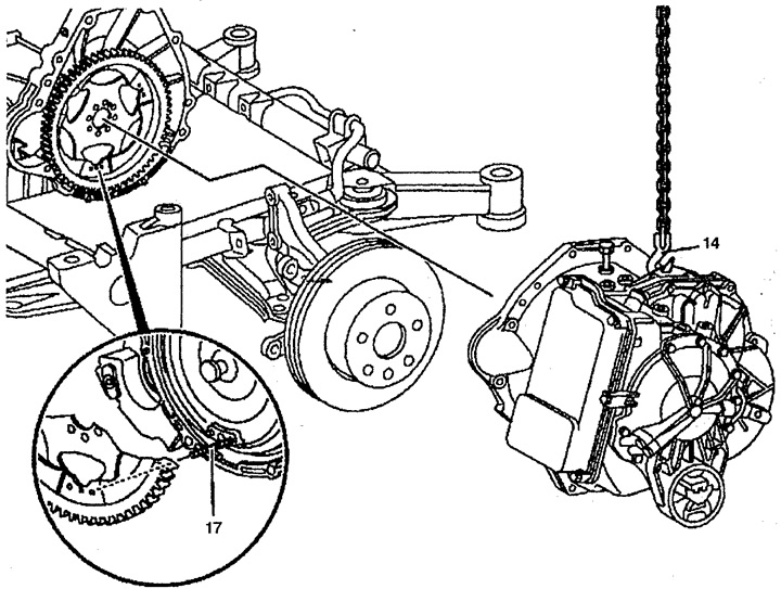
Pic. 6.48. Removal and installation of automatic transmission (vehicles with engines 111.948):
14. Lift,
17. Hairpin.
13. Unscrew the thrust bearing 15 of the gear selector lever.
14. Remove bolt 8.
15. Remove the bridge 10 from the subframe.
16. Install the block 11 between the supporting part of the subframe and the pallet.
17. Lower the gearbox and engine so that the engine sits on block 11.
18. Disconnect the cable from the bracket 13.
19. Turn off bolts 12 of fastening of a transmission and remove an arm 13.
20. Remove the gearbox from the engine using a hoist.
Installation
21. Installation is made in an order, the return to removal. Screw M8 30mm studs into torque converter. When installing the gearbox, the studs 17 must be aligned with the corresponding hole on the drive disk. Do not overtighten the torque converter-to-drive plate mounting bolts.
Removal and installation of automatic transmission (vehicles with engines 601.970)
Removing
1. Disconnect the negative cable from the battery.
2. Drain the fluid from the automatic transmission.
3. Drain the coolant.
4. Disconnect the branch pipe 3 of the cooling system from the tube 1 (see fig.6.47).
5. Unscrew bolts 2 and 4, then move pipe 1 aside.
6. Remove the cover 6 of the Tray.
7. Remove bolts 7. Rotate crankshaft to access all bolts 7. Rotate crankshaft only 120°in direction of rotation.
8. Remove bolts 5.
9. Remove the subframe with the engine.
10. Remove the intermediate shaft.
11. Disconnect the left axle shaft from the flange.
12. Using the lift 14, lift the gearbox with the engine until the gearbox supports 9 are completely unloaded (see fig.6.49).
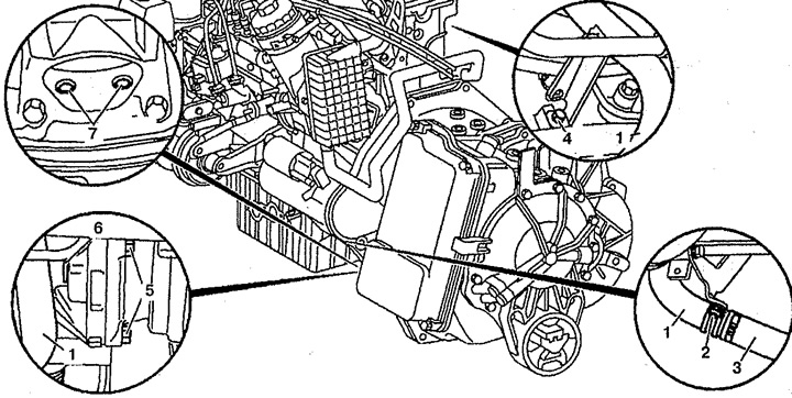
Pic. 6.49. Removal and installation of automatic transmission (vehicles with engines 601.970):
1. Cooling system tube,
2, 4, 5, 7. Bolt,
3. Pipe of the cooling system,
6. Lid.
Pic. 6.49. Removal and installation of automatic transmission (vehicles with engines 601.970):
8. block,
9, 12. Bolt,
10. Gearbox support,
11. Bridge,
13. Bracket,
15. Thrust bearing,
16. Branch pipe of the cooling system.
13. Unscrew the thrust bearing 15 of the gear selector lever.
14. Remove bolt 9.
15. Remove the bridge 11 from the subframe.
16. Install block 8 between the base of the subframe and the pallet.
17. Lower the gearbox and engine so that the engine sits on block 8.
18. Disconnect the cable from the bracket 13.
19. Disconnect the cooling system pipe 16 from the oil cooler.
20. Turn off bolts 12 of fastening of a transmission and remove an arm 13.
21. Remove the gearbox from the engine using a hoist (see fig.6.48).
Installation
22. Installation is made in an order, the return to removal. Screw M8 30mm studs into torque converter. When installing the gearbox, the studs 17 must be aligned with the corresponding hole on the drive disk. Do not overtighten the torque converter-to-drive plate mounting bolts.
Removal and installation of automatic transmission (vehicles with engines 611.980)
Removing
1. Drain the fluid from the gearbox.
2. Remove engine 1 together with gearbox 5 (see fig.6.50).
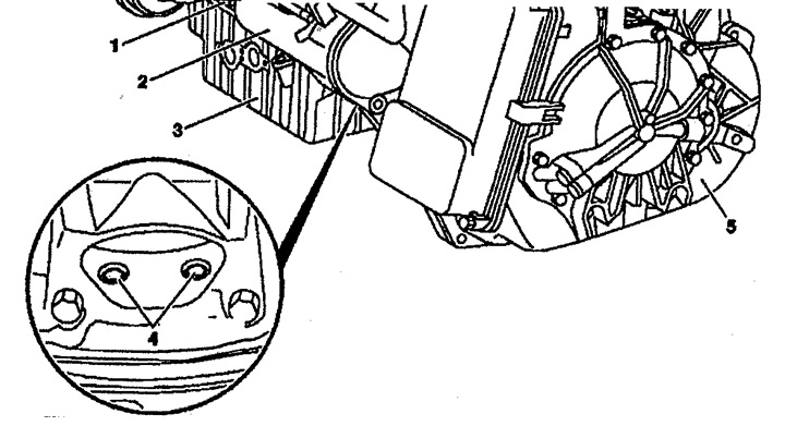
Pic. 6.50. Removal and installation of automatic transmission (vehicles with engines 611.980):
1. Engine,
2. Starter,
3. Pallet,
4. Bolt,
5. Gearbox.
3. Remove the center drive shaft.
4. Unscrew the starter 2 without disconnecting the electrical wiring.
5. Remove the lid on tray 3.
6. Remove bolts 4.
7. Turn off bolts of fastening of a transmission 5.
8. Using the lift 6, disconnect the gearbox 5 from the engine 1 (see fig.6.51).
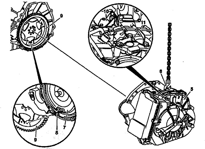
Pic. 6.51. Removal and installation of automatic transmission (vehicles with engines 611.980):
5. Gearbox,
6. Lift,
7. Torque converter,
8. Bolt,
9. Leading disk,
10, 11. Brackets.
9. Turn off an arm 10 fastenings of a cable of a gear change (only if the gearbox is to be replaced).
10. Unscrew the bracket 11 from the gearbox and remove the left flange (only if the gearbox is to be replaced).
Installation
11. Installation is made in an order, the return to removal. Screw the M8 30 mm studs into the torque converter 7. When installing the gearbox 5, the studs 8 must be aligned with the corresponding holes on the drive disk 9. Do not overtighten the torque converter-to-drive disk fastening bolts.
Removal and installation of automatic transmission (vehicles with engines 104.900)
Removing
1. Remove the engine together with a transmission.
2. Drain the transmission fluid.
3. Unscrew the bolts 3 fastening the clamps 4 on the pallet (see fig. 6.52a, 6.526).
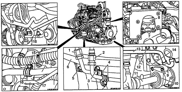
Pic. 6.52a. Removal and installation of automatic transmission (vehicles with engines 104.900):
1, 2. Gearbox oil lines,
3, 5, 7, 9, 12, 15. Bolts,
4, 16. Clamps,
6. Power steering pipe,
8. Gearbox mount,
10. Bearing,
11. Central shaft,
13. Secondary air supply tube,
14, 17. Bracket,
18. Tube of the air conditioning system,
19. Air conditioning compressor.
Pic. 6.52 b. Removal and installation of automatic transmission (vehicles with engines 104.900):
1, 2. Gearbox oil lines,
3, 5, 7, 9. Bolts,
4. clamps,
6. Power steering pipe,
8. Gearbox mount.
4. Unscrew the bolt 27 fastening the clamp 28 on the gearbox 26 (see fig.6.53).
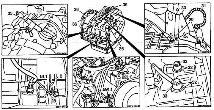
Pic. 6.53. Removal and installation of automatic transmission (vehicles with engines 104.900):
1, 2. Gearbox oil lines,
26. Gearbox,
27, 29, 33. Bolts,
28. Collar,
30. Bracket for fastening the Bowden cable,
31. Wire connection on "mass",
32. Seal,
34. Torque converter,
35. Caliper,
36. Anchor point,
Q91.1. Wiring connector for automatic transmission output shaft speed sensor,
Q92.1. GTR turbine speed sensor wiring connector,
N1.1. Valve wiring connector.
5. Turn off a bolt 5 fastenings of a tube 6 of the amplifier of a steering on the pallet.
6. Turn off bolts 7 fastenings of supports of a transmission 8.
7. Remove starter 20.
8. Disconnect the wiring connector from the valve N1.1.
9. Disconnect the wiring connector from the B91.1 turbine speed sensor and B92.1 driven shaft.
10. Disconnect the wiring connector from the G4 vehicle speed sensor.
11. Turn off bolts 29 of an arm 30 of fastening of a cable of Bowden.
12. Unscrew the banjo bolts 33 and disconnect the oil lines 1 and 2 attached to the gearbox.
13. Unscrew the bolts 9 fastening the bearing 10 of the central drive shaft 11.
14. Turn off bolts 21 of fastening of a back cover 22, then remove it.
15. Unscrew the nuts 23 fastening the torque converter 34 to the drive disk 24.
16. Use support 35 to prevent torque converter 34 from falling.
17. Unscrew the bolt 15 fastening the clamp 16 to the bracket 17.
18. Disconnect the pipes of the air conditioning system 18 from the air conditioning compressor 19.
19. Unscrew the connection wire on "mass" 31 from gearbox 26.
20. Unscrew the bolt 12 fastening the tube 13 of the secondary air supply to the bracket 14.
21. Place a hoist under the transmission and lift it up.
22. Unscrew the safety bolt 25.
23. Remove a transmission together with the hydrotransformer.
24. Remove the drive shaft 11 together with the bearing 10.
Installation
25. Installation is made in an order, the return to removal. Replace the input shaft seal 11.