
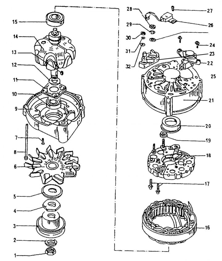
Pic. 310. Bosch alternator device: 1 - nut, 50 Nm; 2 - washer; 3 - pulley; 4 - thrust washer; 5 - washer; 6 - cooling impeller; 7 - bolt; 8 - tightening bolt; 9 - front cover of the generator; 10 - bearing on the drive side; 11 - bearing retaining plate; 12 - thrust ring; 13 - key; 14 - rotor; 15 - rear bearing; 16 - stator; 17 - bolt; 18 - rectifier block; 19 - plastic insulating sleeve; 20 - plastic bearing sleeve; 21 - generator housing; 22 - voltage regulator; 23 - insulating washer; 24 — a bolt of fastening of a voltage regulator; 25 - washer; 26 - capacitor; 27 - bolt; 28 - nut, 16 Nm; 29 - spring ring; 30 - output nut «D+»; 31 - spring ring; 32 - washer
Work on disassembling the generator must be carried out in the following order (pic. 310):
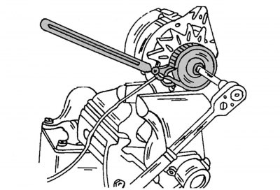
Pic. 311. Unscrewing the pulley fastening nut
- unscrew the rotor shaft nut and remove the pulley, fan and spacer from the shaft. At the same time, the shaft can be kept from turning by installing an old V-belt on the pulley, and clamping the generator in a vice (pic. 311), or you can install a hexagon into the end of the shaft and unscrew the nut. To remove the pulley, use a two- or three-legged puller. Pay attention to the fact that the installed pulley is suitable for this type of engine;
- remove the key from the shaft;
- unscrew the voltage regulator together with the brush holder and remove it (see description above);
- mark the relative position of the front cover and the generator housing and unscrew the two coupling bolts from the housing. Remove the cover, for which, if necessary, use a plastic hammer;
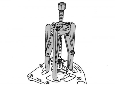
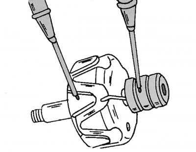
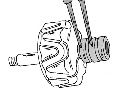
Pic. 312. Removing the drive-side bearing from the rotor
- clamp the cover with the installed rotor in a vise and remove the rotor with a three-legged puller, as shown in fig. 312. When the rotor is pressed out, the bearing retaining plate bolts can be torn out. Therefore, when installing the puller, make sure that its legs are behind the plate, and not just behind the cover. If you need to remove the bearing, unscrew the bolts from the inside and press out the bearing;
- remove the bearing from the rotor shaft. If a puller is used, insert it under the bearing inner race;
- unsolder the rectifier unit from the stator. At the same time, to remove heat, hold the wires at the soldering points with tongs. Overheating of diodes is unacceptable. It is recommended to remove diodes if you have the appropriate tools and experience.
Checking brushes and brush holder
Check contact of brushes with slip rings. Check the mobility of the brush carbons in the guides, if necessary, clean the brush holder with a grease-removing liquid.
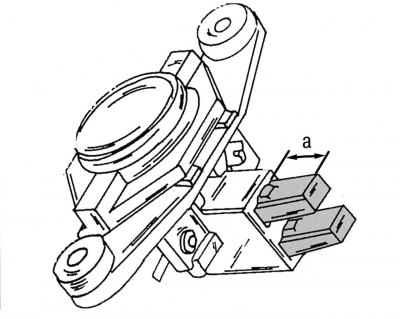
Pic. 309. Measuring the length of brushes (a - not less than 5.0 mm)
If the protruding part of the brushes is less than 5.0 mm (see fig. 309), the brushes need to be replaced. Use a ruler to measure.
Rotor check
Pic. 313. Method of connecting an ohmmeter to check the short circuit of the rotor winding on «mass»
If the slip rings are dirty or covered with grease, wipe them with a cloth soaked in a grease-dissolving liquid. Scratches can be buffed out with the finest grit sandpaper. To check the insulation, attach the contact wires of an ohmmeter to the rotor core and slip rings. If the resistance value does not tend to infinity, the rotor must be replaced (pic. 313).
Pic. 314. Checking the rotor for a short circuit or open circuit
Check the rotor winding for electrical conductivity, for which both contact wires of the ohmmeter are attached to the slip rings (pic. 314). The resistance value should be between 2.8 and 3.0 ohms. If the value tends to infinity, the circuit is broken or there is a short in it. In both cases, it is necessary to replace the rotor or install a serviceable, used generator.
Stator check
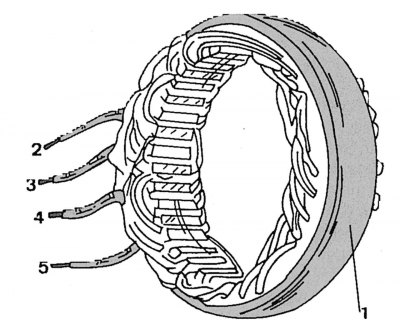
Pic. 315. Checking the stator winding for a short circuit
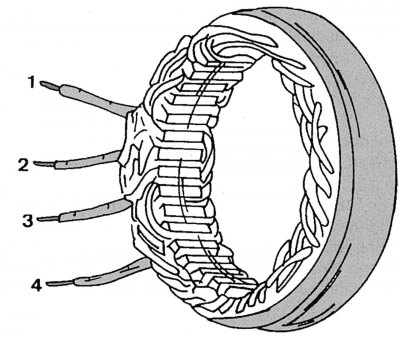
Pic. 316. Checking the stator winding for an open circuit
In the event of a short circuit, the location of the damage can be determined visually due to the resulting burnout. Otherwise, apply one ohmmeter lead to the outer ring 1 (pic. 315) stator, and the other - in turn to the conclusions 2, 3, 4, 5 of the stator winding. The device should show infinity. To check the winding for an open circuit, connect the ohmmeter contacts in turn between the terminals of the stator winding 1 and 2; 1 and 3; 1 and 4; 2 and 3; 2 and 4; 3 and 4 (pic. 316). If the value tends to infinity, the chain is broken. The normal resistance value should be 0.10-0.11 ohms.
Checking Rectifier Diodes
An accurate test of diodes for the transmission of forward voltage and the determination of reverse current are possible only with the help of a special device, so it is better to entrust it to specialists.
Assembly
When assembling, use Fig. 310, which shows the generator device. Tighten the pulley fastening nut to 80 Nm. Also pay attention to the correct installation of the brushes.
Possible generator malfunctions
Cause of malfunction Remedy A. Red warning lamp does not light up when the ignition is turned on 1. The battery is discharged Start the engine «smoking» or using a tow 2. Break in the wire from the battery Check the wires and battery terminals, replace if necessary 3. Burnt out lamp Replace the lamp 4. Break in the wire between the ignition switch, control lamp and generator Check the circuit with a tester 5. Break in the wire «masses» between alternator and housing Check wire 6. Worn brushes Replace brushes 7. Faulty voltage regulator Replace regulator 8. Faulty alternator Repair alternator 9. Alternator got wet during washing Blow out with compressed air B. Red indicator lamp lights up or flashes when engine is running 1. Belt defective drive Check drive 2. Wire contacts Check 3. See A6, A7, A8