
Petrol models
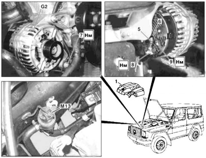
Generator Installation Details on Gasoline Models
1 - Air cleaner; 5 - Terminal 30 wire (B+); 6 - Terminal 61 wire (D+); 7 - Bolts; 8, 9 - Nuts; G2 - Generator; M13 - Circulation pump of the cooling system
1. Disconnect the negative cable from the battery.
2. Remove the air cleaner (1) (see chapter Power supply and exhaust systems).
3. Loosen the drive belt and slip it off the alternator pulley.
4. Unscrew from the cover of the valve mechanism and take aside the guide tube of the measuring probe.
5. Remove the circulation pump of the cooling system installed in the wheel arch (M13).
6. Turn out fixing bolts (7), remove the alternator (G2) from the support bracket and set it aside.
7. Disconnect the wiring (5, 6) and finally remove the generator (G2).
8. Installation is carried out in the reverse order.
9. In conclusion, clear the memory of the processor of the on-board self-diagnosis system (see Section general information).
Diesel models
Models 463.323 (M612)
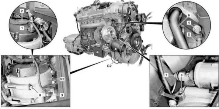
Alternator installation details on models 463.323 (M612)
1 - Connector; 2 - Wiring circuit 30; 3, 4, 8 - Bolts; 5 - Turbocharger oil line; 6, 7 - Coolant supply lines; G2 - Generator
1. On models of the corresponding configuration (code ET2) activate the service mode of the TELE AID emergency call system (see Section Activation / deactivation of the service mode of the TELE AID emergency call system).
2. Connect a booster battery to the original battery.
3. Disconnect the negative cable from the battery.
4. Jack up the car and put it on stands.
5. Remove the crankcase protection.
6. Empty the cooling system (see chapter Ongoing care and maintenance).
7. Remove trim panels from cylinder head cover.
8. Remove the air cleaner (see chapter Power supply and exhaust systems).
9. Remove the accessory drive belt (see chapter Engine).
10. Remove an air duct of system of pressurization.
11. Disconnect the connector (1) circuit wiring 61.
12. Disconnect circuit 30 wiring (2).
13. Turn out a bolt (3) support bracket.
14. Turn out a bolt (4) and remove the coolant line (on the crankcase and turbocharger), also remove the coolant supply line (6), - prepare replacement sealing elements.
15. Remove the bolt from the bracket (7).
16. Turn out fixing bolts (8) and, lowering down, remove the generator (G2), - prepare a replacement gasket to be installed between the cooling jacket flange and the engine block. Remove the drive pulley if necessary (see below).
17. Installation is carried out in the reverse order - do not forget to replace the sealing elements.
18. Deactivate the service mode of the TELE AID system and clear the memory of the processor of the on-board self-diagnosis system (see Section general information).
19. Finally, start the engine and check it for signs of developing coolant leaks.
Models 463.333 (M628)
Water cooled generator
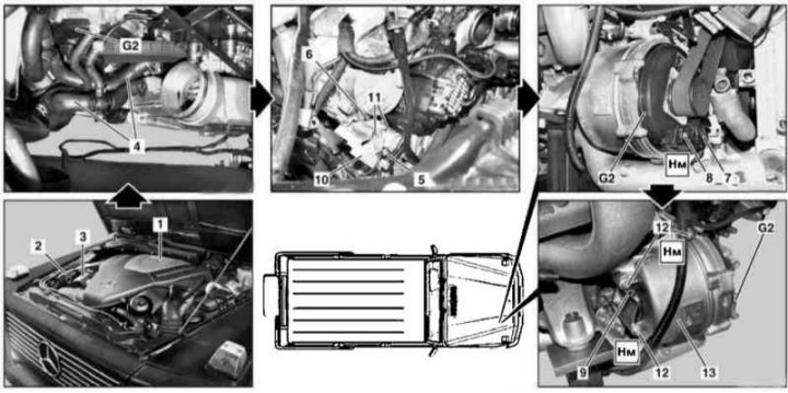
Details of installing a water-cooled generator on models 463.333 (M628)
1 - Air cleaner; 2 - Air intake; 3 - Cover; 4 - Hoses of the cooling path; 5, 6, 9 - Screws; 7 - Wiring connector; 8 - Nut fastening to the generator terminals B +; 10 - Support bracket; 11, 12 - Bolts; 13 - Cooler casing; G2 - Generator
1. On models of the corresponding configuration (code ET2) activate the service mode of the TELE AID emergency call system (see Section Activation / deactivation of the service mode of the TELE AID emergency call system).
2. Disconnect the negative cable from the battery.
3. Jack up the car and put it on stands.
4. Remove the crankcase protection.
5. Empty the cooling system (see chapter Ongoing care and maintenance).
6. Remove the air cleaner (1) and air intake (2) (see chapter Power supply and exhaust systems).
7. Remove cover (3).
8. Remove the fan shroud and radiator (see chapter Refrigeration, heating, ventilation and air conditioning systems).
9. Remove the charge air cooler (see chapter Power supply and exhaust systems).
10. In order to provide access, remove the laid in front of the generator (G2) hoses (4) cooling path.
11. Remove the accessory drive belt (see chapter Engine).
12. Turn out a bolt (5) fixing the line of the cooling path.
13. Turn out a bolt (6) and remove the dipstick guide tube.
14. Disconnect the wiring connector (7).
15. Loosen the nut (8) fasteners to the generator terminals B + and release the electrical wiring.
16. Turn out a bolt (9) fixing the wiring harness.
17. Turn out fixing bolts (11) and remove the support bracket (10) control module.
18. Turn out bolts (12) cooler shroud fixings (13).
19. Press the generator (G2) complete with cooler cover (13) to the right and, moving forward, remove it from the engine compartment - prepare replaceable sealing rings.
20. Installation is carried out in the reverse order. Make sure that the guide tube of the measuring probe is tight and correctly connected to the air cleaner of the air intake (2).
21. Finally, deactivate the service mode of the TELE AID system, clear the memory of the processor of the on-board self-diagnosis system (see Section general information) and check the engine for signs of developing coolant leaks.
Air cooled generator
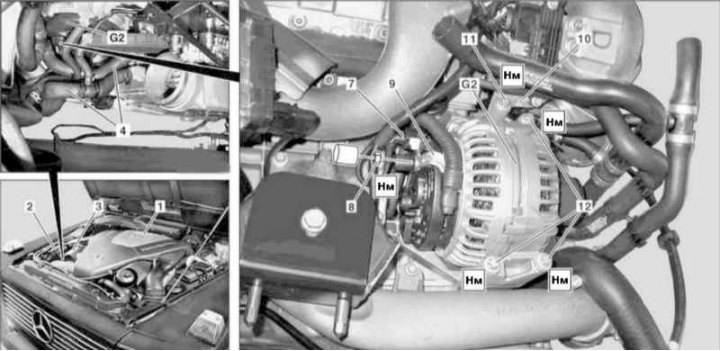
Details of installation of the generator with air cooling on models 463.333 (M628)
1 - Air cleaner; 2 - Air intake; 3 - Cover; 4 - Hoses of the cooling path; 7 - Wiring connector; 8 - Nut fastening to the generator terminals B +; 9 - Wiring; 10 - Support bracket; 11, 12 - Bolts; G2 - Generator
1. On models of the corresponding configuration (code ET2) activate the service mode of the TELE AID emergency call system (see Section Activation / deactivation of the service mode of the TELE AID emergency call system).
2. Disconnect the negative cable from the battery.
3. Jack up the car and put it on stands.
4. Remove the crankcase protection.
5. Empty the cooling system (see chapter Ongoing care and maintenance).
6. Remove the air cleaner (1) and air intake (2) (see chapter Power supply and exhaust systems).
7. Remove cover (3).
8. Remove the fan shroud and radiator (see chapter Refrigeration, heating, ventilation and air conditioning systems).
9. Remove the charge air cooler (see chapter Power supply and exhaust systems).
10. In order to provide access, remove the laid in front of the generator (G2) hoses (4) cooling path.
11. Remove the accessory drive belt (see chapter Engine).
12. Disconnect the wiring connector (7).
13. Loosen the nut (8) fasteners to the generator terminals B + and release the electrical wiring (9).
14. Turn out fixing bolts (11) and remove the bracket (10).
15. Turn out bolts (12) and remove the alternator (G2), if necessary, remove the drive pulley (see below).
16. Installation is carried out in the reverse order.
17. Finally, deactivate the service mode of the TELE AID system, clear the memory of the processor of the on-board self-diagnosis system (see Section general information) and check the engine for signs of developing coolant leaks.
Removing the drive pulley
Note. The alternator pulley must be replaced without fail if the mileage of its use exceeds 100,000 km.
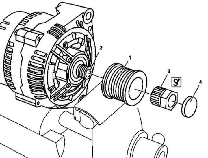
Details of installation of a drive pulley of the generator on diesel models
1 - Pulley; 2 - Generator shaft; 3 - End head; 4 - Plug
1. Remove the generator (see above).
2. Remove the plug (4), - the plug must be replaced without fail.
3. Using socket (3) unbolt the pulley (1), - shaft (2) the generator is kept from turning with a hex or knurled head.
4. Installation is carried out in the reverse order.