
Attention! Self-locking fasteners must be replaced without fail!
Petrol models
463.250 (M112)
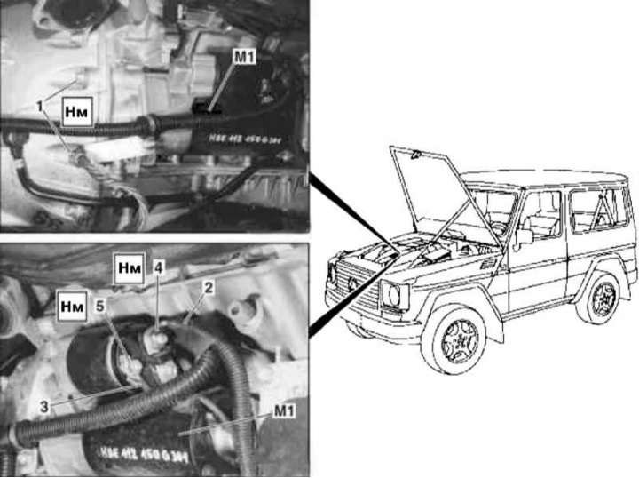
Details of installation of a starter on models 463.250 (M112) (1 of 2)
1 - Screws; 2 - Contour line 30; 3 - Contour line 50; 4, 5 - Nuts; M1 - Starter
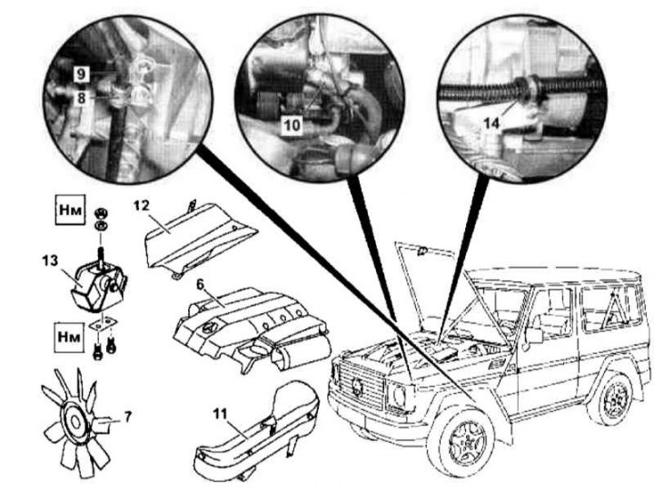
Details of installation of a starter on models 463.250 (M112) (2 of 2)
6 - Air cleaner; 7 - Fan of the cooling system; 8, 14 - Brackets; 9 - ATF line; 10 - Power steering return line; 11 - Left shield; 12 - Right shield; 13 - Right suspension support of the power unit
1. Disconnect the negative cable from the battery.
2. Remove the air cleaner (6) (see chapter Power supply and exhaust systems).
3. Remove the viscous cooling fan assembly (7) (see chapter Refrigeration, heating, ventilation and air conditioning systems).
4. Unscrew the right and left supports of the power unit from the frame.
5. Unbolt the bracket (8) ATF line attachments (9) right and left bottom and top on the oil pan.
6. Disconnect the line (10) steering pump, - plug open fittings immediately.
7. Release the electrical wiring from the clamp and unbolt the left shield from the frame (11).
8. Unscrew the right shield from the frame (12).
9. Hang the engine from above and, slightly moving it to the side, if necessary, remove the shield (12).
10. Loosen and remove the right suspension support of the power unit (13) (see chapter Engine).
11. Unbolt the bracket (14) and disconnect the wiring of circuits 30 and 50 (2 and 3).
12. Remove the screws (1) and remove the starter (M1).
13. Installation is carried out in the reverse order - make sure that when lowering the power unit, the shields are not pinched (11 and 12).
14. In conclusion, clear the memory of the processor of the on-board self-diagnosis system (see Section general information).
463.246/249 (M113)
Details of installation of a starter on models 463.246/249 (M113) as shown in the illustration Starter installation details on models 463.250 (M112) (1 of 2).
1. Disconnect the negative cable from the battery.
2. Disconnect the wiring of circuits 30 and 50 (2 and 3).
3. Remove the fixing screws (1) and remove the starter (M1).
4. Installation is carried out in the reverse order.
5. In conclusion, clear the memory of the processor of the on-board self-diagnosis system (see Section general information).
Diesel models
463.323 (M612)
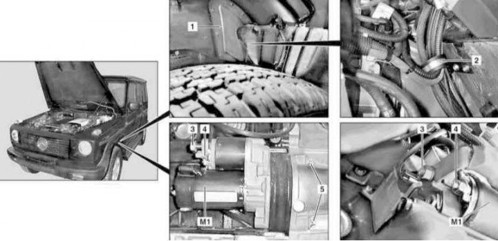
Details of installation of a starter on models 463.323 (M612)
1 - duster; 2 - Retainer; 3 - Wiring circuit 30; 4 - Wiring circuit 50; 5 - Bolts; M1 - Starter
1. On models of the corresponding configuration (code ET2) activate the service mode of the TELE AID emergency call system (see Section Activation / deactivation of the service mode of the TELE AID emergency call system).
2. Disconnect the negative cable from the battery.
3. Jack up the car and put it on stands.
4. Remove the left front wheel.
5. Remove the left front splash guard.
6. Remove the boot (1).
7. Loosen the latch (2), remove the harness and set aside the wiring harness.
8. Remove the cover and disconnect the wiring (3) circuit 30.
9. Disconnect circuit 50 wiring (4).
10. Turn out fixing bolts (5) and through the wheel arch remove the starter (M1).
11. Installation is carried out in the reverse order.
12. Finally, deactivate the service mode of the TELE AID system, clear the memory of the processor of the on-board self-diagnosis system (see Section general information).
463.333 (M628)
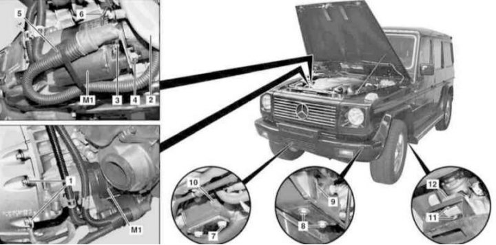
Details of installation of a starter on models 463.333 (M628)
1 - Screw; 2 - Right lower air duct; 3, 4 - Nuts; 5 - Wiring circuit 30; 6 - Wiring circuit 50; 7, 8, 11 - Bolts; 9, 10, 12 - Suspension bearings of the power unit; M1 - Starter
1. Disconnect the negative cable from the battery - to avoid the risk of a short circuit, do not connect an auxiliary battery.
2. Jack up the car and put it on stands.
3. Remove the air cleaner (see chapter Power supply and exhaust systems).
4. Remove the crankcase protection.
5. Disconnect the right lower air duct (2) (see chapter Power supply and exhaust systems).
6. Loosening nuts (3 and 4), disconnect the wiring of circuits 30 and 50 (5 and 6).
7. Hang the engine from above.
8. Removing the bolts (7 and 8), loosen the powertrain front suspension mounts (9 and 10).
9. Giving back the bolts (11), loosen the rear support (12).
10. Raise the unit by releasing the front supports and slide it back so that the support (10) hit the mark.
11. Turn out fixing bolts (1) and remove the starter (M1).
12. Installation is carried out in the reverse order.
13. In conclusion, clear the memory of the processor of the on-board self-diagnosis system (see Section general information).