
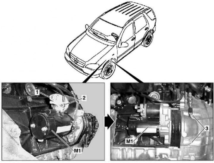
Details of installation of a starter on models 163.136 and 163.113 (111 and 612 series engines)
1 - Terminal 30; 2 - Terminal 50; 3 - Screws; M1 - Starter
1. Details of the starter installation on models 163.136 and 163.113 are shown in the illustration, to which all references in the text refer.
2. Disconnect the negative cable from the battery.
3. Remove the left front wheel and wheel arch protection locker.
4. Disconnect wiring from terminals 30 (1) and 50 (2) starter.
5. Turn out fixing bolts (3) and remove the starter assembly (M1).
6. Install in reverse order, remember to follow the battery connection procedures.
Models 163.154/157/173/174/175
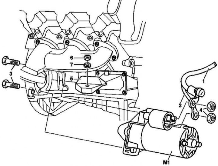
Details of installation of a starter on models 163.154/157/173/174/175 (112 and 113 series engines)
1 - Terminal 30; 2 - Terminal 50; 3 - Bolts; 4 - Nut; 5 - Shield of the suspension support of the power unit; 6 - Nut; 7 - Washer; M1 - Starter
1. Starter installation details on models 163.154/157/173/174/175 are shown in the illustration, to which all references in the text refer.
2. Disconnect the negative cable from the battery.
3. Remove the right front wheel and wheel arch protection locker.
4. Give the fixing nut (6) and remove the shield of the suspension support of the power unit (5).
5. Disconnect wiring from terminals 30 (1) and 50 (2) starter.
6. Turn out fixing bolts (3) and remove the starter assembly (M1).
7. Install in reverse order, remember to follow the battery connection procedures.
Models 163.128
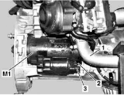
Details of installation of a starter on models 163.128 (628 series engines)
1 - Lower branch pipe of the air path; 2 - Terminal 50; 3 - Terminal 30; M1 - Starter
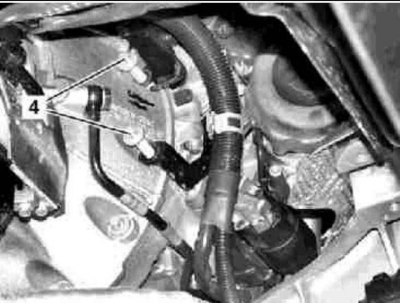
Details of installation of a starter on models 163.128 (628 series engines)
4 - Bolt
1. Details of the starter installation on models 163.128 are shown in the illustrations, which include all references in the text.
2. Disconnect the negative cable from the battery.
3. Remove the bottom section of the soundproofing.
4. Remove the right lower air path (1) and take it aside without disconnecting it from the air duct.
5. Remove the protective cap and disconnect the electrical wiring from terminals 20 (3) and 50 (2) starter.
6. Turn out fixing bolts (4) and remove the starter assembly (M1).
7. Install in reverse order, remember to follow the battery connection procedures.