
The generator has bearings filled with long-life grease and does not require regular maintenance. The external surfaces of the generator must be kept clean and free of water or other liquids.
The alternator brushes are in contact with smooth slip rings and are therefore durable. To check the brushes, if this work is performed for the first time, it is necessary to remove the generator. In a generator with a voltage regulator installed on the rear side, work is carried out in the following sequence:
Disconnect the ground wire from the battery and disconnect the plug from the generator.
Unscrew the brush holder / voltage regulator (black box) to the alternator and remove the brush holder. In order to avoid damage to the brushes when removing, reject the voltage regulator.
Measure the length of the brushes as shown in fig. 265. If the length of the brushes is less than 5 mm, it is necessary to unsolder the wires in the places shown by the arrows.
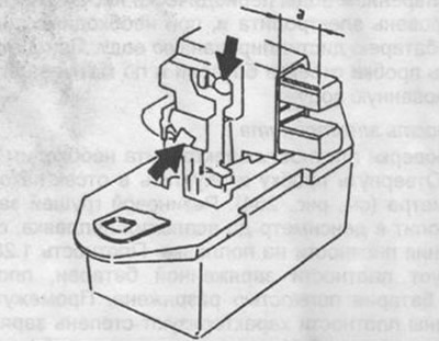
Pic. 265. The protrusion of the brushes must be at least 5 mm.
Solder the wires of the new brushes and assemble in reverse order. Check the free movement of the brushes in the guides.
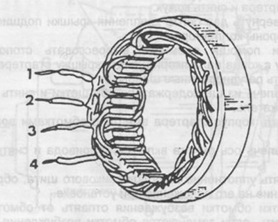
If the voltage regulator is installed separately from the brush holder, the generator must be removed and the brush holder removed. In this case, measure the length of the brushes as shown in fig. 266.
Pic. 266. Measuring the length of brushes (see text).
With some experience, you can disassemble the generator.
Disassembly
Guided by Fig. 267, do the following:
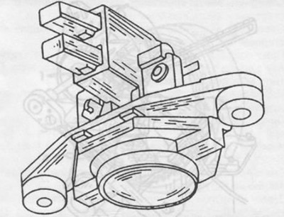
Unscrew the fastening nut from the rotor shaft and remove the pulley, fan and spacer. To do this, fix the generator in a vise, as shown in Fig. 268, and, holding the pulley from turning with the old V-belt, unscrew the nut. Otherwise, you can fix the shaft with a hexagon inserted into the end of the shaft and unscrew the nut. Remove the pulley using a puller. When installing the pulley, pay attention to its dimensions so that the pulley matches the engine model.
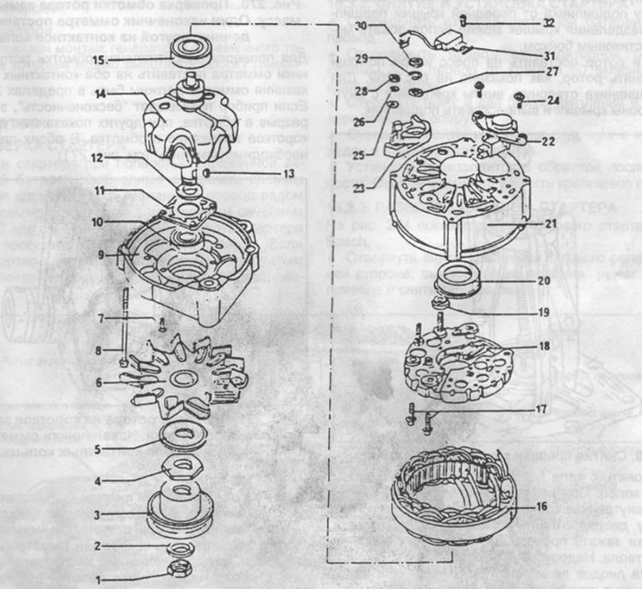
Pic. 267. Installation of alternator firm Bosch.
1 - nut, tightening torque 50 Nm,
2 - washer,
3 - pulley, diameter 74 mm,
4 - remote washer,
5 - washer,
6 - fan,
7 - screw,
8 - screw,
9 - drive side cover,
10 - bearing on the drive side,
11 - bearing cap,
12 - remote ring,
13 - key,
14 - rotor,
15 - bearing from the side of slip rings,
16 - stator,
17 - screw,
18 - diode plate,
19 - plastic washer-insulator,
20 - plastic sleeve,
21 - generator housing,
22 - voltage regulator,
23 - plastic insulator plate,
24 - screws,
25 - washer,
26 - spring washer,
27 - puck,
28 - terminal nut "D+",
29 - spring washer,
30 - nut, tightening torque 16 Nm,
31 - noise suppression capacitor,
32 - screw.
Pic. 268. Unscrewing the pulley mounting nut. Slide the V-belt over the pulley as shown.
Remove the key from the shaft.
Unscrew the voltage regulator mount and brush holder and remove it.
Mark the position of the cover on the drive side and the generator housing relative to each other and unscrew the two fastening screws from the housing. Disconnect the rear bearing cap from the front bearing cap. A hammer with a plastic head can be used to separate the lids.
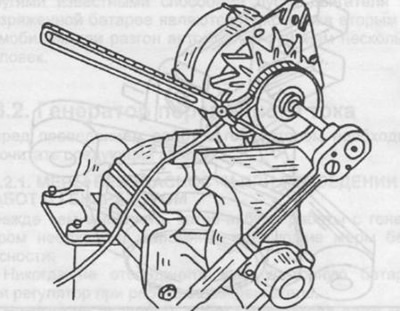
Put the lid and rotor on the press and use a puller to remove the rotor, as shown in fig. 269. To remove the bearing, unscrew the fastening screws from the inside of the cover and press out the bearing.
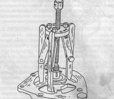
Pic. 269. Removing the cover from the generator rotor.
Press the bearing from the slip ring side of the rotor shaft. When using a puller, attach it to the inner race of the bearing.
Unsolder the diode plate from the stator. To do this, clamp the wires at the soldering points with tongs to ensure heat dissipation. It is unacceptable to overheat the diodes.
Installation of diodes is possible only if you have the necessary tools and skills.
Checking brushes and brush holder
Check contact of brushes and slip rings. Check the mobility of the brushes in the guides, if necessary, wipe the brushes with gasoline.
If the brush protrudes from the brush holder by less than 5 mm, it must be replaced. The measurement is made with a ruler.
Rotor check
Wipe dirty or greasy ring contacts with a cloth soaked in gasoline. Random scratches on the working surface should be polished with a fine emery cloth.
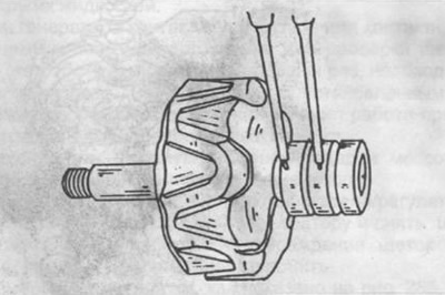
To check the insulation of the rotor winding, put one tip of the ohmmeter on the rotor core, and the other on the contact ring. If the device does not show "infinity", the rotor needs to be replaced (see fig. 270).
Pic. 270. Checking the rotor winding by shorting to ground. Place one tip of the ohmmeter on the core, the other on the contact ring.
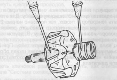
To check the resistance of the rotor winding, put the ohmmeter tips on both slip rings. The ohmmeter reading should be within 2.8.. 3.4 ohms. If the device shows "infinity", this means a break in the winding, otherwise indicates a short circuit in the winding. In both cases, the rotor must be replaced (see fig. 271).
Pic. 271. Checking the rotor for a short circuit or open circuit in the winding. Place the tips of an ohmmeter on both contact rings.
Stator check
In the event of a short circuit, strong heating occurs at the site of damage, so the site of damage can already be detected by visual inspection. In addition, install one tip of the ohmmeter on the stator plate and connect the other tip in series with the four leads of the stator winding (see fig. 272). The instrument should show "infinity". To check the stator windings, it is necessary to check the resistance of each of the four windings (see fig. 273). The resistance value should be within 0.10... 0.14 Ohm.
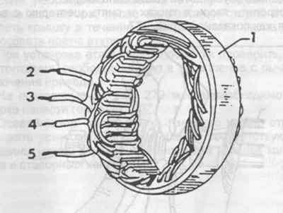
Pic. 272. Checking the stator windings for a short circuit. Put the ohmmeter tips on the stator plate and connect the second tip in series with terminals 2,3,4 and 5. Ohmmeter readings "infinity".
Pic. 273. Connecting an ohmmeter in series to the stator winding terminals 1 and 2,1 and 3,1 and 4, 2 and 3, 2 and 4, 3 and 4. The measurement results are described in the text.
Diode test
Accurate testing of diodes is possible only when using special devices in specialized workshops.
Generator Assembly
On fig. 267 shows the installation of an alternator. using which you can assemble the generator.