
Unscrew the screws securing the traction relay on the front side, disengage the drive enable lever and remove the traction relay.
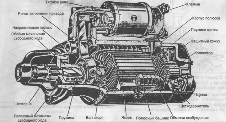
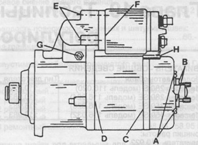
Pic. 274. Section of a Bosch starter.
Loosen the cover screws on the back of the starter and remove the cover.
Loosen the two bearing cap bolts on the manifold side.
Using a puller, press the locking sleeve off the end of the armature shaft and remove the starter cover. Save the shims.
Remove both brushes from the brush holder and remove the brush holder.
Remove the starter housing together with the excitation windings.
Remove the axle of the drive engagement lever and remove the lever.
Remove the seal from the endshield, paying attention to its installation position.
Solder the excitation winding brushes from the winding and replace if the excitation windings are replaced. When replacing the excitation windings, perform the following work:
Loosen the four screws securing the pole shoes by tapping on the brass barb (see fig. 275).
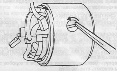
Pic. 275. Unscrewing the screws securing the pole shoes with the help of a beard.
Remove the pole shoes and remove the excitation windings together with the brushes from the shoes.
To remove the anchor or gear, you can use the recommendations of Fig. 276.
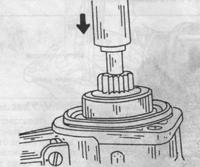
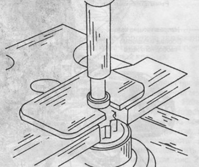
Pic. 276. The arrow shows the direction of pressing the ring with a shoulder from the end of the starter drive. Below is the retaining ring.
Using a piece of pipe of the appropriate diameter, press it down (shown by arrow) collared ring and release the circlip.
Remove the circlip from the armature shaft groove.
Remove burrs from the end of the armature shaft.
Fix the armature in a vise and remove the gear from the armature shaft, as shown in fig. 277.
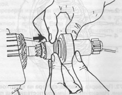
Pic. 277. Removing the starter drive mechanism from the armature shaft.
All details (except for excitation windings if they are to be reused) clean with gasoline and check carefully. Check the armature windings for signs of overheating and the collector. With slight wear of the collector, it can be cleaned with a fine emery cloth, with heavy wear, the collector must be machined on a lathe with minimal metal removal.
The starter drive gear cannot be disassembled and must be replaced if damaged. The gear must move freely along the armature shaft, otherwise it must be replaced.
The starter assembly is carried out in the reverse order, as during disassembly. The minimum allowable brush length is 13 mm. When installing new brushes, remove the old brushes and clean their ends, to which the strands of wires are soldered, unsolder the strands. Flatten the end of the core, put on a new brush and solder.
Pay special attention to the following points when assembling the starter:
Put the gear on the shaft, install the thrust ring and fix the new circlip on the shaft. Place the retaining ring on the tool (see fig. 278) and press a snap ring into it, which will eliminate pressure on the armature shaft.
Pic. 278. Pressing the retaining ring into the thrust ring.
If it is necessary to replace the bearing sleeve in the manifold cover, after pressing out the old sleeve, heat the cover for 5 minutes in hot oil and press in a new sleeve.
When installing the retracting winding, check that the pusher freely engages with the drive engagement lever.
On those shown in Fig. 279 places it is necessary to apply sealant during assembly "DZ".
Pic. 279. The letters indicate the places where sealant must be applied before assembly.
The armature axial clearance is 0.1...0.3 mm, it can be adjusted by installing a support washer of appropriate thickness between the bearing bush in the collector cover and the circlip.