
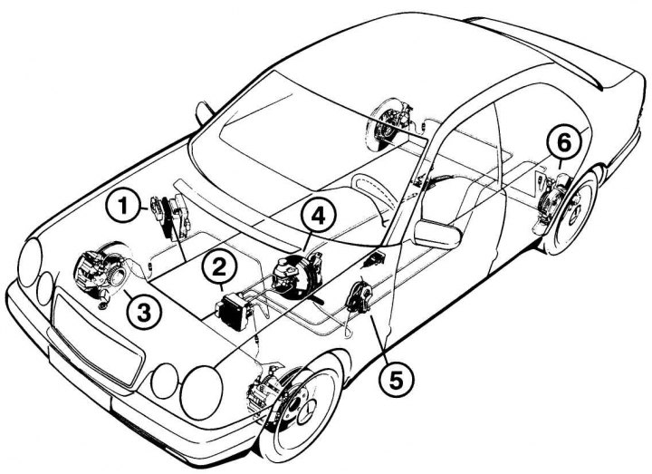
Pic. 8.1. Scheme of individual elements of the ABS system: 1 - control unit; 2 - brake mechanism of the front wheel with a speed sensor; 3 – hydraulic block; 4 – the main brake cylinder with the amplifier; 5 – parking brake mechanism; 6 - rear wheel brake mechanism with speed sensor
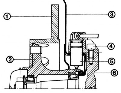
Pic. 8.2. Installing speed sensors on the front wheels: 1 - brake disc; 2 - front wheel hub; 3 - shield; 4 - a bolt with an internal hexagon, 25 Nm; 5 - speed sensor; 6 - steering knuckle
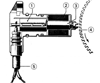
Pic. 8.3. Wheel speed measurement: 1 - speed sensor; 2 - coil; 3 - magnetic core; 4 - gear rotor; 5 - coaxial wire
ABS control unit (pic. 8.1)
Continuously processes information from the wheel speed sensors and compares it with the programmed values. If the difference in values indicates the risk of blocking when braking one or more wheels, the control unit activates the hydraulic unit, which reduces the working pressure in the brake system of the corresponding wheel until it gains free play and brakes again. Depending on the condition of the roadway, this cycle during one braking takes place in a matter of milliseconds.
Hydraulic block
This is the main assembly of the ABS system, installed in the front left side of the engine compartment. Includes electric pump and valve block with solenoid valves. When you press the brake pedal, the brake master cylinder pressurizes the brake fluid through the valve block to the wheels. In this case, the valve block regulates the pressure in each of the hydraulic drives of the system that combines the front wheel and the rear wheel located diagonally from it. When the ABS is activated, the control unit sends a command in the form of an electrical signal: «Decrease fluid pressure». Brake fluid in this case in a small circle through the valve block returns to the reservoir. The operation of the pump can be seen by a slight pulsation of the brake pedal.
Wheel speed sensors
Each sensor 5 (pic. 8.2) mounted on its wheel, at a short distance from the toothed disk (pulse rotor), attached directly to the hub.
Disc serrations 4 (pic. 8.3) depending on wheel speed (speed) move faster or slower past the magnetic core 3 of the sensor 1. Each tooth of the disk induces a brief increase in voltage in the coil 2 as it passes. Its frequency depends on the rotational speed of the rotor and, accordingly, the wheel. Through coaxial wire 5, an electrical signal enters the control unit.
Thus, information about the wheel speed is transmitted as an electrical signal to the control unit.
Relay
The corresponding relays are responsible for the operation of the solenoid valves and the electric pump. They are mounted on a holder under the ABS control unit.
Abnormalities in the ABS system
The ABS warning lamp comes on when the ignition is switched on and goes out if the engine is running, within 2 seconds at the latest. If the lamp continues to burn, then there is a malfunction in the ABS system. Nevertheless, you can continue driving - the brakes will function as on a car without ABS. To eliminate the malfunction, you should contact the Mercedes service center, where they will diagnose the system control unit using a special device.