
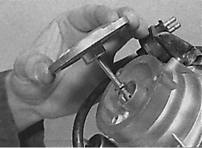
Removing the carburetor shock absorber cover together with the piston vibration damper
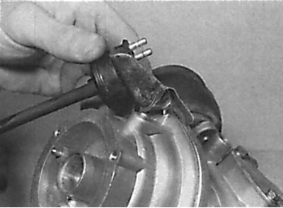
Removing the shock absorber from the carburetor body
The location of the screw that also secures the delay valve
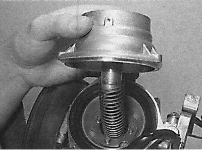
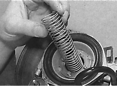
Removing the Piston Return Spring
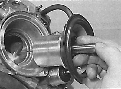
Extraction in the form of a single block of the piston, diaphragm and jet needle
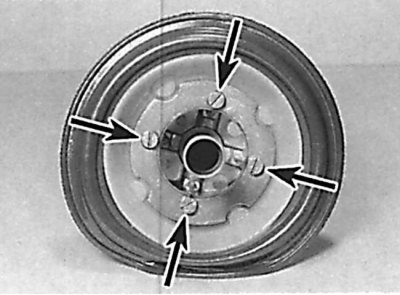
The location of the piston diaphragm fastening screws
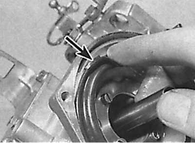
Alignment of the protrusion on the outer edge of the diaphragm with the notch on the carburetor body
1. Unscrew the screws and remove the carburetor shock absorber cover together with the piston vibration damper (see fig. Removing the carburetor shock absorber cover together with the piston vibration damper). Remove the seal from the cover.
2. Unscrew the screws and remove the shock absorber from the piston housing. When doing this, keep in mind that one of these screws secures the delay valve (see fig. Removing the shock absorber from the carburetor body, Location of the screw that also secures the delay valve).
3. Remove the piston return spring, then remove the piston, diaphragm and jet needle as a single unit from the carburetor body (see fig. Piston return spring removal Piston, diaphragm and jet needle removal as a single unit).
4. Check the condition of the piston diaphragm. If the diaphragm has defects in the form of cracks or through holes, the operation of the carburetor will be impaired. Replace the diaphragm, for which, while holding the piston, unscrew the screws securing the diaphragm, remove the washer and diaphragm from the piston (see fig. The location of the piston diaphragm fastening screws).
5. Install a new diaphragm onto the piston so that the protrusion on the back of the diaphragm aligns with the notch on the surface of the piston.
6. Place the washer on the diaphragm and secure with screws.
7. Install the piston, diaphragm and jet needle assembly into the carburetor body so that the protrusion on the outer edge of the diaphragm aligns with the notch on the carburetor body (see fig. Alignment of the protrusion on the outer edge of the diaphragm with the notch on the carburetor body). Check that the air hole on the piston base is on the engine side.
8. Install the piston return spring, then the shock absorber and secure with screws, noting that one of the screws secures the delay valve.
Attention! To avoid diaphragm displacement during installation, do not rotate the shock absorber. Install shock absorber cover with piston damper with new gasket and secure with screws.
9. Unscrew the fill plug from the shock absorber and add the required oil to the shock absorber until the oil level is below the bottom of the fill plug hole. Screw the fill plug into place.
Jet needle
Piston block, diaphragm and jet needle
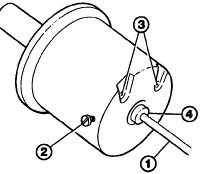
1 - jet needle; 2 - screws for fastening the jet needle; 3 - air channel; 4 - plastic sleeve
1. Remove the block with the piston, diaphragm and jet needle from the carburetor.
2. On the side of the piston, loosen the screw and remove the jet needle (see picture).
3. Check the condition of the jet needle. If it is contaminated, wash the needle in an appropriate solvent. Do not damage the needle while doing this. If the needle is worn out, replace it.
4. Install the needle into the piston so that the plastic sleeve is aligned with the piston body and secure the needle with the screw.
5. Install the piston block with the jet needle into the carburetor body.
Delay valve
1. Check the operation of the delay valve on a cold engine. Turn on the ignition without starting the engine. Disconnect the longer vacuum hose from the carburetor body and create a vacuum in it. In the first 5-15 seconds, air should pass through the valve, after which the valve should close. If air passes through the valve constantly or does not pass at all, the valve is defective and must be replaced.
2. Remove the short bent vacuum hose from the valve base. Disconnect the electrical connector from the valve.
3. Unscrew the screw and remove the delay valve from the carburetor.
4. Installation is made in sequence, return to removal.
Throttle Control Diaphragm
1. Label and disconnect the electrical connectors and vacuum hoses from the throttle body.
2. Unscrew the screws and remove the casing of the bimetal spring from the damper casing. At the same time, do not disconnect the coolant supply hoses. Remove the gasket.
3. Remove the connecting rod from the spherical seat on the throttle lever.
4. Remove the three screws and remove the throttle body from the carburetor body. Remove the gasket.
5. Remove the circlip and remove the throttle lever along with the gasket.
6. Loosen the screws and remove the throttle control diaphragm cover and gasket.
7. Remove the retaining ring and move forward the drive lever with the fast idle cam so that the diaphragm link can be disconnected.
8. Remove diaphragm and rod from throttle body.
9. Check the condition of the diaphragm and, if there are defects in the form of cracks or through holes, replace it.
10. Install the diaphragm and linkage into the throttle body, then install the spring and cover with a new gasket and secure with screws.
11. Connect the throttle control lever to the throttle control diaphragm rod and secure with the circlip.
12. Adjust the position of the throttle lever by moving the diaphragm rod up to the stop, and the drive lever to the left so that it is installed opposite the diaphragm rod (i.e. to the fast idle position). In this case, the throttle lever should be installed in the center of the second step from the top on the fast idle cam. Otherwise, to install the drive lever, bend its shoulder.
13. Move the drive lever all the way to the left to the engine start position. When doing this, the throttle lever should be set on the top step of the fast idle cam. Otherwise, bend the lever arm to install the drive lever.
14. Move the drive lever to the right as far as it will go to the normal idle position. The choke lever must not rest on the steps of the fast idle cam.
15. After adjusting the damper lever, remove the lever, install the protective gasket, then reinstall the lever and secure with the circlip.
16. Install the throttle body with a new gasket to the carburetor and secure with screws.
17. Install the bimetal spring housing with a new gasket on the damper body so that the protrusion of the spring is aligned with the damper drive lever. Align the marks on the damper and bimetal spring housings and fix the bimetallic spring housing with screws.
18. Attach the linkage to the spherical seat of the throttle valve.
19. Connect the electrical connectors and vacuum hoses to the damper body in accordance with the previously made markings.