
Damper actuator
PIERBURG carburettor choke actuator
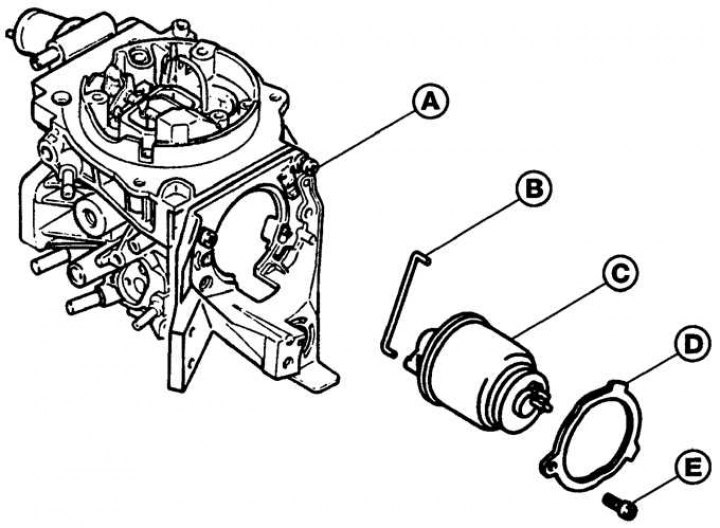
A - carburetor body; B - thrust; C - body of the actuator; D - fixing ring; E - screw
1. Remove the air filter.
2. Disconnect the electrical connectors from the actuator.
3. Unscrew the screw and remove the actuator mounting ring (see fig. PIERBURG carburettor choke actuator).
4. Disconnect the linkage from the choke lever, then rotate the actuator housing, remove the locking pin and remove the actuator from the carburetor.
5. Installation is made in sequence, return to removal.
Throttle actuator
PIERBURG carburetor actuator
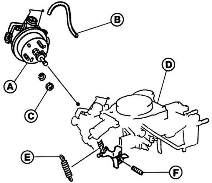
And – the body of the executive mechanism; B - vacuum hose; C - nut; D - carburetor body; E - spring; F - adjusting screw
1. Remove the air filter.
2. Disconnect the electrical connector and vacuum hose from the side of the actuator.
3. Unscrew the three nuts and remove the actuator from the carburetor (see fig. PIERBURG carburetor actuator).
4. Installation is made in sequence, return to removal. Check that the clearance between the actuator rod and the screw on the throttle lever should be between 1.5 and 2.5 mm.
Coolant temperature sensor
Location of the coolant temperature sensor on the cylinder head
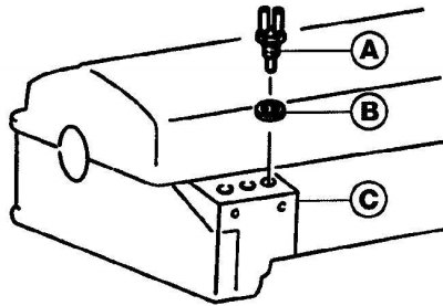
And – the gauge of temperature of a cooling liquid; B - sealing ring; C - cylinder head
1. The coolant temperature sensor is installed at the front of the cylinder head (see fig. Location of the coolant temperature sensor on the cylinder head).
2. Disconnect the electrical connector from the sensor.
3. Check that the engine is cold, then briefly unscrew the cap from the expansion tank in order to relieve pressure in the cooling system.
4. Unscrew the coolant temperature sensor and remove the O-ring.
5. The performance of the coolant temperature sensor can be checked by heating it in a container of water. Use a thermometer to determine the water temperature. Having connected an ohmmeter to the sensor contacts, measure the resistance of the sensor at various temperatures.
6. Installation of the sensor of temperature of a cooling liquid is made in sequence, return to removal.
Electronic control device (ecu)
Attention! Electronic control device (ECU) contains parts sensitive to static electricity, so when disconnecting the electrical connectors from the unit (ECU) do not touch the connector contacts with your hands or tools, as this may damage the elements of the ECU. When handling the ECU, discharge static electricity from your body by touching grounded metal objects. Disconnect the electrical connectors from the ECU only for the time needed for repairs.
The ECU is located in the rear right side of the engine compartment.
1. Remove the ground wire from the battery.
2. Release the brackets and remove the ECU cover.
3. Squeeze the retaining clips on the ECU and remove the multi-pin electrical connector from the ECU. When removing the connector, be careful not to damage the connector pins.
4. Remove the screws and remove the ECU.
5. Installation is made in sequence, return to removal.