
Attention! A lifting mechanism must be used to remove the cylinder head. When installing the cylinder head, a new gasket must be used. A new bolt must be used to secure the camshaft bearing that controls the intake valves.
Removing
Cylinder head
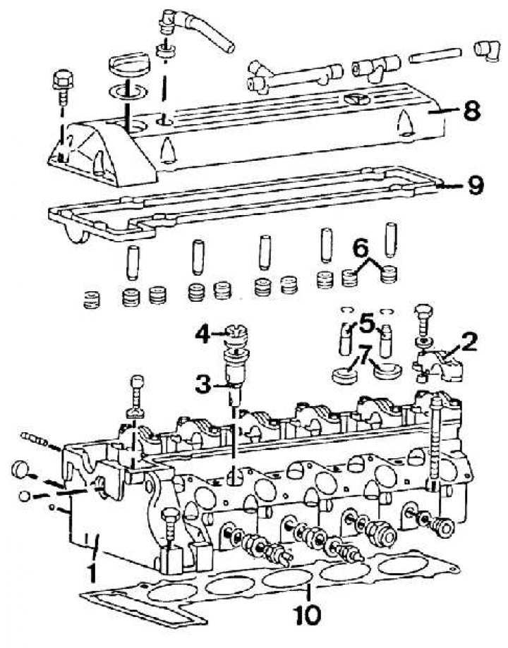
1 – a head of the block of cylinders; 2 - bearing cover; 3 - vortex chamber; 4 - nut for fastening the vortex chamber; 5 - valve guides; 6 - oil seals; 7 - valve seats; 8 – a cover of a head of the block of cylinders; 9 – a lining of a cover of a head of the block of cylinders
Elements of the auxiliary drive belt tensioner
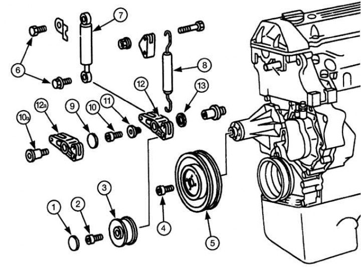
1 - plastic cover; 2 - bolt; 3 - intermediate pulley; 4 - bolt; 5 - radiator fan; 6 - bolts; 7 - shock absorber strut of the tension mechanism; 8 - springs; 9 - plastic plug; 10 - bolt; 10a - a bolt of another design; 11 - bushing; 12 - tension mechanism; 12a - tension mechanism of another design; 13 - gasket
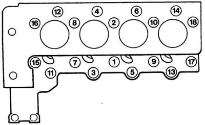
Cylinder head bolt tightening sequence on a 4-cylinder diesel engine
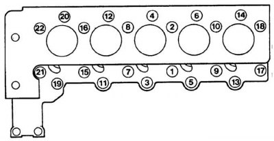
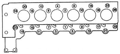
The sequence of tightening the cylinder head bolts on a 5-cylinder diesel engine
The sequence of tightening the cylinder head bolts on a 6-cylinder diesel engine
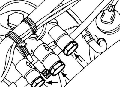
Fuel line connections to the fuel filter
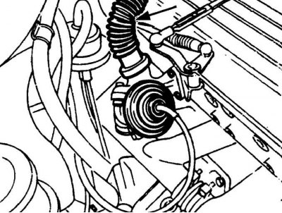
Hose connection to the exhaust gas re-burning valve
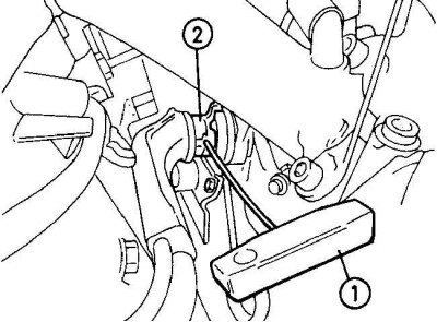
Using a special tool (1) to release the retaining clip (2) from the coolant elbow connection to the oil cooler
1. The cylinder head is removed on a cold engine along with the manifolds.
2. Remove the ground wire from the battery.
3. Open the hood and place it in a vertical position.
4. Drain the engine oil from the engine.
5. Remove the camshaft.
6. Remove fuel injectors.
7. Remove the radiator.
8. Remove the auxiliary drive belt tensioner (see fig. Elements of the auxiliary drive belt tensioner).
9. Remove the plastic plug, unscrew the bolt and remove the auxiliary drive belt idler pulley.
10. Unscrew the bolts and remove the radiator fan pulley.
11. Unscrew bolts and remove an amortization rack of the mechanism of a tension.
12. Using pliers, remove the tensioner spring.
13. Remove the plastic plug, unscrew the bolt and remove the auxiliary drive belt tensioner.
14. On non-turbo models, remove the air filter cover, air intake tube, and air filter element.
15. On models with a turbocharger, remove the air intake pipe from the turbocharger.
16. Unscrew the turbocharger bracket hanger.
17. Unscrew the nut and disconnect the turbocharger oil return pipe from the cylinder head.
18. Place a clean rag under the fuel line connection to the fuel filter. Then unscrew the nuts and disconnect the fuel lines (see fig. Fuel line connections to the fuel filter). Close the ends of the pipelines with plugs.
19. Unscrew the fuel filter from the cylinder head.
20. Unscrew the pipe for the engine oil dipstick from the cylinder head.
21. Remove the hose from the EGR valve (see fig. Hose connection to the exhaust gas re-burning valve).
22. Working under the vehicle, remove the bolts securing the exhaust support bracket to the transmission, then remove the bolts and remove the bracket from the exhaust system.
23. Disconnect the exhaust pipe from the intake manifold.
24. Using the special tool, disconnect the retaining clip from the coolant elbow and oil cooler junction (see fig. Using a special tool to release the retaining clip from the coolant elbow to oil cooler connection).
25. Unscrew the elbow from the oil cooler, then disconnect it from the connector.
26. Unscrew the nuts securing the supply rail to the glow plugs.
27. Remove the intake manifold.
28. Remove the upper drive chain guide.
29. Through the hole in the cylinder head, unscrew the two bolts securing the cylinder head to the drive chain cover (see fig. Arrangement of bolts of fastening of a cover of a driving chain to a head of the block of cylinders).
30. Check that all hoses and electrical connectors are disconnected from the cylinder head.
31. Gradually and evenly unscrew the cylinder head bolts in the reverse order shown in the figures Cylinder head bolt tightening sequence on a 4-cylinder diesel engine, Cylinder head bolt tightening sequence on a 5-cylinder diesel engine, Cylinder head bolt tightening sequence on a 5-cylinder diesel engine, Head bolt tightening sequence cylinders on a 6-cylinder diesel engine.
32. Remove the cylinder head bolts, noting their location, as bolts of different lengths are used.
33. Hook the slings of the lifting mechanism to the lugs located on the left front side of the cylinder head and on the rear right side of the exhaust manifold, and remove the cylinder head from the engine.
34. Remove the cylinder head gasket.
Preparing for installation
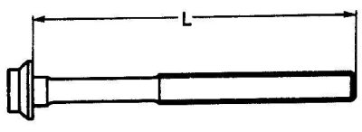
Measuring the length of the cylinder head bolt
1. The mating surfaces of the engine head and cylinder block must be thoroughly cleaned of the remnants of the old gasket and soot using a plastic or wooden scraper. It is also necessary to clean the tops of the pistons. When cleaning, exclude the possibility of cleaning products in the oil channels of the cooling system. Thoroughly clean the inner surfaces of the cylinders.
2. Check the mating surfaces of the engine head and cylinder block for defects. Minor damage is eliminated by machining. Also using a metal ruler and feeler gauge, check the flatness of the surfaces.
3. Clean the bolt holes in the block. Screwing a bolt into an oil-filled hole can rupture the block due to hydraulic pressure.
4. Measure the length of the cylinder head bolts (see fig. Measuring the length of the cylinder head bolt). If the bolt length exceeds the allowable limits, the bolts must be replaced as a set.
Installation
1. Check that the timing marks on the camshaft and crankshaft are aligned with the pointers.
2. Check that the two guide pins are installed in the cylinder block and install the cylinder head gasket.
3. Using a lifting mechanism, install the cylinder head.
4. Lubricate the cylinder head bolts with engine oil, insert them into the head and tighten by hand.
5. Gradually and sequentially in several stages tighten the cylinder head bolts (see fig. Cylinder head bolt tightening sequence for 4-cylinder diesel engine, Cylinder head bolt tightening sequence for 5-cylinder diesel engine, Cylinder head bolt tightening sequence for 6-cylinder diesel engine).
6. Screw in and tighten bolts of fastening of a cover of a driving chain to a head of the block of cylinders to the demanded moment.
7. Install the upper chain guide.
8. Install the intake manifold.
9. Install the supply rail on the glow plugs and secure with nuts.
10. Soak a new O-ring in clean coolant and install it on the elbow. Install the elbow to the oil cooler and secure with the retaining clip.
11. Connect the exhaust pipe to the exhaust manifold.
12. Install the exhaust system mounting bracket to the gearbox and secure with bolts.
13. Further installation is carried out in the reverse order of removal, taking into account the following points.
14. Install the auxiliary drive belt tensioner in the reverse order of removal.
15. Pour coolant into the engine cooling system.
16. Fill the engine with engine oil.