
Removing
1. Remove the ground wire from the battery.
2. Unscrew the cap from the reservoir of the brake system and add brake fluid to the mark max. Put a piece of polyethylene on the neck of the refill tank and screw on the cap. This seals the top of the reservoir tank, resulting in minimal loss of brake fluid during further work.
3. Clean the connection point of the brake pipes to the hydraulic device and mark the location of the brake pipes. Unscrew the union nuts and disconnect the pipes from the hydraulic device and close the ends of the pipes with plugs.
4. Loosen the screw and remove the relay cover from the hydraulic unit. Disconnect the electrical connector from the hydraulic device, then unscrew the bolt and remove the ground bar.
5. Unscrew the nuts and remove the hydraulic device from the bracket.
Attention! Do not disassemble the modulator unit, as it cannot be repaired.
Installation
1. Installation is carried out in the reverse order of removal, taking into account the following points:
- a - check the condition of the rubber bushings and, if necessary, replace them;
- b - connect the brake pipes to the hydraulic unit and secure them with union nuts, tightening them to the required torque;
- c - bleed the hydraulic system before installing the pressure accumulator.
Electronic control device (ECU)
Removing
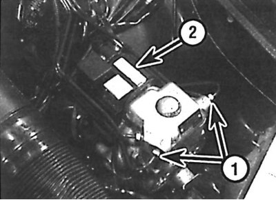
Connecting the brake pipes (1) and electrical connector (2) to the hydraulic device of the anti-lock brake system
Location of the electronic control device for controlling the anti-lock brake system
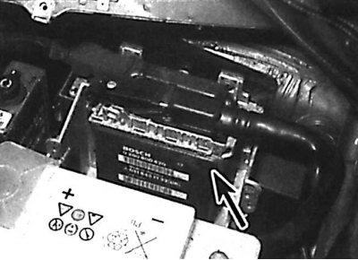
1. The ABS electronic control is located under a plastic cover and mounted on the back of the battery tray. Remove the ground wire from the battery.
2. Remove the rubber seal and cover. To improve access to the electronic control device, remove the rubber seal located at the base of the windshield, then disconnect the mounting bracket, unscrew the screws and remove the side of the ventilation shroud.
3. Release the mounting bracket and disconnect the electrical connector from the ECU, then remove the ECU from the socket (see fig. Location of the electronic control device for controlling the anti-lock brake system).
Installation
1. Installation is made in sequence, return to removal.
Front wheel sensor
Removing
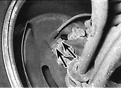
Arrangement of bolts of fastening of the gauge of a forward wheel
1. Apply the parking brake, then raise the front of the vehicle and support it on stands. Remove the corresponding front wheel.
2. Check that the ignition is off, then remove the electrical connector from the mounting bracket and disconnect it from the main wiring harness. Remove the sensor wiring from the mounting brackets and clamps.
3. Unscrew the bolt that secures the sensor to the steering knuckle, and remove the sensor along with the wires (see picture). Check the condition of the sensor O-ring and replace it if necessary. When installing the sensor, you must use a new mounting bolt.
Installation
1. Clean the wheel sensor and the grooves of the wheel sensor rotor from dirt. Apply a thin layer of grease to the mating surfaces of the sensor and steering knuckle.
2. Install the sensor o-ring.
3. Install the wheel sensor in the steering knuckle and secure with new bolts, tightening them to the required torque.
4. Secure the sensor wire with brackets and clamps. Check that the O-ring of the electrical connector is in good condition, then connect the electrical connector and secure it with the clip.
5. Install the wheel, then lower the vehicle to the ground and tighten the wheel bolts to the correct torque.
Rear wheel sensor
Attention! When installing the sensor, you must use a new mounting bolt.
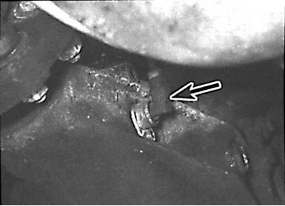
Location of the rear wheel sensor on the rear final drive housing
1. Raise the rear of the car and secure it on stands.
2. To improve access to the electrical connector of the sensor, remove the rear seat.
3. Check that the ignition is OFF, then disconnect the sensor electrical connector from the wiring harness. Release the sensor wiring from the mounting brackets so that it can be removed with the sensor.
4. Working under the vehicle, remove the sensor harness from the brackets holding it to the underside of the vehicle.
5. Unscrew the mounting bolt and remove the sensor with the O-ring from the rear final drive housing (see picture). Check the condition of the sensor O-ring and replace it if necessary. When installing the sensor, you must use a new mounting bolt.
Installation
1. Clean the mating surfaces of the sensor and rear final drive housing and install a new sensor O-ring.
2. Install the sensor in place and secure it with a new bolt, tightening it to the required torque.
3. Pass the sensor electrical connector through the rubber seal in the underside of the vehicle, then in the vehicle interior, connect the electrical connector to the main wiring harness. Secure the sensor wiring harness with brackets.
4. Install the rear seat and lower the car.
Front wheel sensor gear rotor
The front wheel sensor gear rotor is mounted on the rear of the wheel hub. Clean the grooves and check the condition of the rotor teeth. If a rotor replacement is required, the hub assembly must be replaced.
Rear wheel sensor gear rotor
The rear wheel sensor gear rotor is an integral part of the rear final drive. Remove the rear wheel sensor and check the condition of the rotor teeth through the sensor hole. To replace the rear wheel sensor gear rotor, the rear final drive must be dismantled and this work must be done at a service station.
Protection relay
Removing
1. The protection relay is located next to the electronic control device (ECU). Before removing the relay, check that the ignition is off.
2. Unscrew the mounting screw, pull the relay out of its socket and remove it from the engine compartment.
Installation
1. Check the condition of the protective relay connectors on the relay and in the relay socket.
2. Installation is made in sequence, return to removal.
Anti-lock braking system relay
Removing
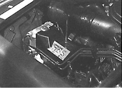
Unscrewing the screw securing the relay cover to the hydraulic device
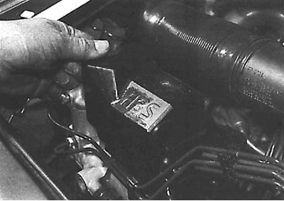
Removing the relay cover from the hydraulic unit
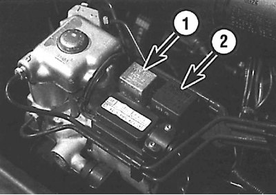
Solenoid valve relay location (1) and return pump relay (2) anti-lock brakes
1. Unscrew the screw and remove the relay cover from the hydraulic device (see fig. Unscrewing the screw securing the relay cover to the hydraulic unit, Removing the relay cover from the hydraulic unit)
2. Check that the ignition is off and remove the required relay from the control unit. The solenoid valve relay is smaller than the return pump relay (see fig. Location of the solenoid valve relay and anti-lock braking system return pump relay).