
Removing
1. Set the rear suspension of the car to the position "Service Mode" (only on vehicles with rear air suspension).
2. Disconnect the negative cable from the battery.
3. Drain the refrigerant from the air conditioning system (if it is installed).
4. Drain the coolant.
5. Remove the bottom soundproofing.
6. Remove bumper 3 (see fig.4.1).
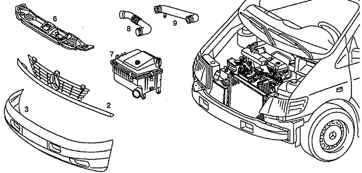
Pic. 4.1. Removing the engine:
2. Radiator grille,
3. Bumper,
6. Front cross beam,
7. Air filter,
8, 9. Air sampling tubes.
7. Remove the radiator grille 2, the front transverse pillar 6, the air filter 7, the air intake pipe 9.
8. Disconnect the engine wiring.
9. Disconnect the wiring connectors from the radiator.
10. Disconnect the pipe of the cooling system 13 from the adapter 12 (see fig.4.2). Check branch pipe 13 and its fastening collar, if necessary, replace them.
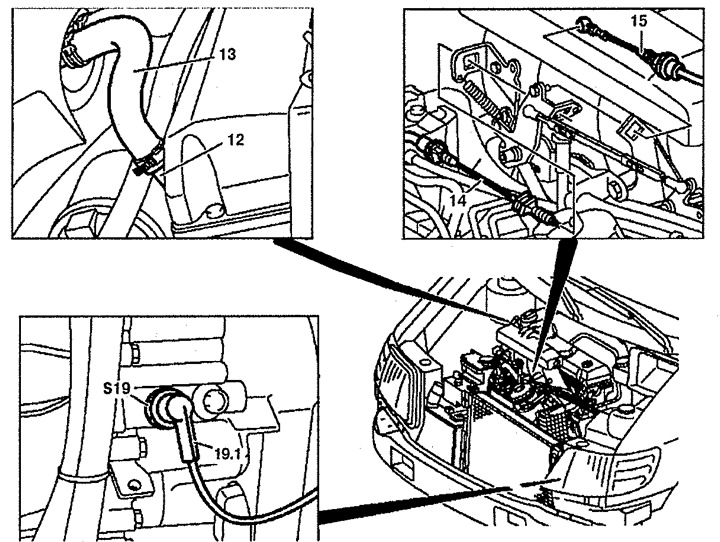
Pic. 4.2. Removing the engine:
12. Adapter,
13. Branch pipe of the cooling system,
14. Thrust control fuel supply,
15. Bowden cable,
S19. Stoplight switch,
S19.1. Brake light switch wiring connector.
11. Disconnect draft 14 of management of giving of fuel from an arm.
12. Disconnect the accelerator pedal position sensor from the Bowden cable 15 (only on cars with automatic transmission).
13. Disconnect the wiring connector from the brake light switch S19 (only on cars with automatic transmission).
14. Unscrew the pipes of the air conditioning system 20 from the expansion valve (only on vehicles with air conditioning).
15. Cut the straps (arrows) fixing fuel lines 22 and 25 and vacuum tubes 23 and 24 (see fig.4.3). When installing the tape must be replaced.
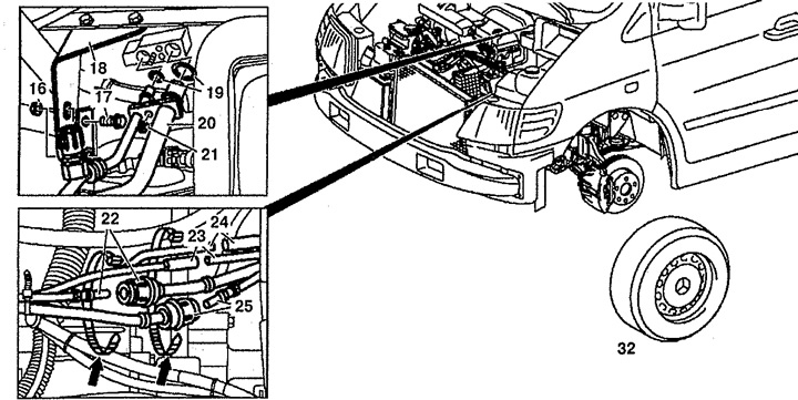
Pic. 4.3. Removing the engine:
16, 21. Nut,
17. Bolt,
18. Bracket,
19. Oil seals,
20. Tubes of the air conditioning system,
22. Drain fuel line,
23, 24. Vacuum tubes,
25. Fuel injection line,
32. Wheel.
16. Remove vacuum tubes 23 and 24.
17. Disconnect fuel lines 22 and 25.
18. Disconnect the shift lever.
19. Remove the front wheels 32.
20. Remove the air heater.
21. Unscrew the shock absorber mount 67 (see fig.4.4).
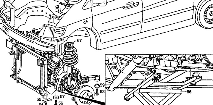
Pic. 4.4. Removing the engine:
54, 56. Bolt,
55. Front limiter,
57, 59. Gasket,
65. Subframe,
66. Jack,
67. Mounting the shock absorber.
22. Remove the brake calipers 35 (see fig.4.5). Do not stretch the brake hoses.
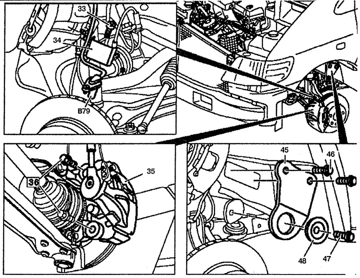
Pic. 4.5. Removing the engine:
33, 36, 46, 47. Bolt,
34. Protective shield,
35. Brake caliper,
45. Stove,
48. Support bushing,
B79. ABS sensor.
23. Remove the B79 ABS sensors and protective shield 34 from the steering knuckles.
24. Remove the support bushings 48 and plates 45 on both sides of the wheel arches.
25. Disconnect connector X106 from automatic transmission (see fig.4.6).
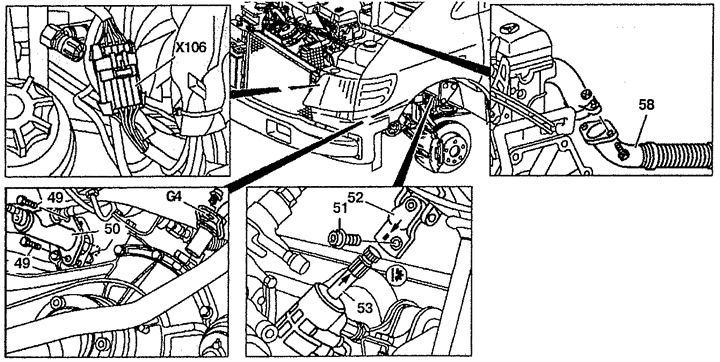
Pic. 4.6. Removing the engine:
49, 51. Bolts,
50. Clutch slave cylinder,
52. Cardan joint of the steering shaft,
53. Steering gear,
58. Exhaust pipe,
G4. Speed sensor,
X106. Automatic transmission connector.
26. Disconnect the clutch slave cylinder 50 from the gearbox. do not disconnect piping.
27. Remove the G4 speed sensor from the transmission. Do not disconnect electrical wiring.
28. Using a marker, mark the relative position of the steering gear 53 and the universal joint of the steering shaft 52 (arrow).
29. Remove bolt 51.
30. Disconnect the connection on "mass" from the frame.
31. Disconnect the exhaust pipe 58 from the manifold.
32. Install the jack 66 under the engine subframe 65 (see fig.4.4).
33. Secure all disconnected pipes and wiring on the side so that it does not interfere with the removal of the engine.
34. Slowly lower subframe 65.
35. Disconnect axle shafts 1 and 7 from the flanges and fix them on the side (see fig.4.7).
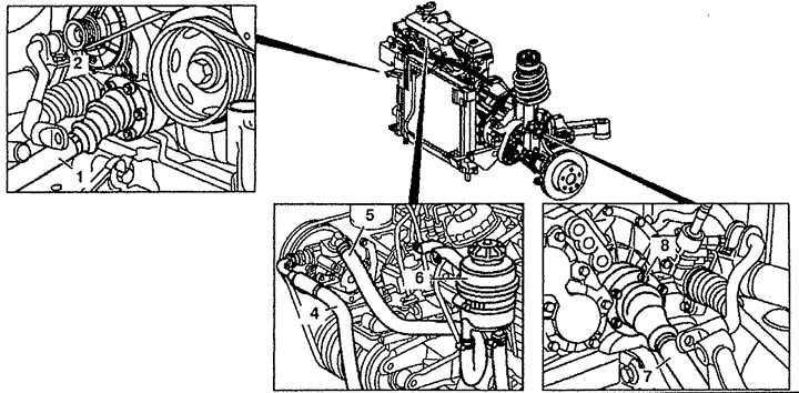
Pic. 4.7. Removing the engine:
1. Right half shaft,
2, 8. Bolt,
4. Discharge pipeline,
5. Drain pipeline,
6. Power steering reservoir,
7. Left axle.
36. Remove the fluid from the power steering reservoir 6. Disconnect the pressure 4 and drain 5 pipelines from the power steering pump.
37. Remove the radiator.
38. Cut the strap (arrow) fixing the pipes of the air conditioning system and remove the tank 13 from the bracket together with the pipes and disconnect them (see fig.4.8).
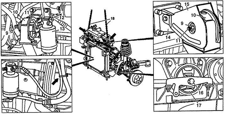
Pic. 4.8. Removing the engine:
9. Nut, 10. Front engine mount,
11, 16. Bolt,
12. Engine front bracket,
13. Tank,
14. Engine rear bracket,
15. Protective plate,
17. Gearbox support,
18. Lift.
39. Raise the engine using the hoist 18 until the gearbox is disengaged from the supports.
40. Unscrew the bolts 11 fastening the supports 1214 14 of the engine to the brackets 10.
41. Unscrew the bolt 16 of the gearbox 17.
42. Remove the engine by lifting it to the required height.
Installation
43. Installation is carried out in the reverse order of removal.