
Removing
1. Disconnect the negative cable from the battery.
2. Drain the coolant.
3. Remove intake manifold 13 (see fig.4.15).
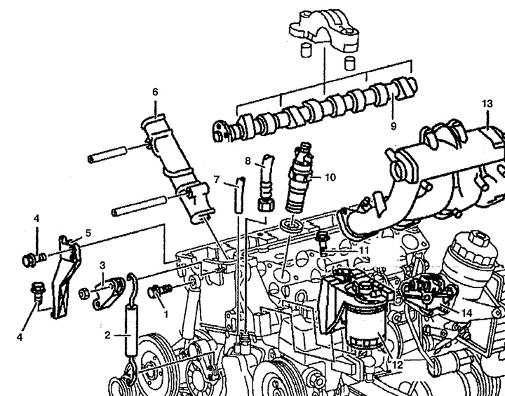
Pic. 4.15. Cylinder head:
1, 4, 11. Bolt,
2. Spring,
3. Spring tension lever,
5. Support,
6. Sliding lever,
7, 8. Vacuum tubes,
9. Camshaft,
10. Nozzle,
12. Fuel filter,
13. Intake manifold,
14. Fuel cooler.
4. Remove nozzles 10.
5. Remove fuel lines and fuel cooler 14.
6. Turn off bolts 11 and disconnect the fuel filter 12 together with the attached tubes.
7. Remove the alternator drive belt.
8. Remove spring tension lever 3 and spring 2.
9. Turn off a bolt 1 fastenings of a damper to a head of the block of cylinders.
10. Disconnect vacuum tubes 7 and 8 from the vacuum pump.
11. Disconnect a support 5 from an arm of the generator.
12. Remove the camshaft 9.
13. Remove the sliding lever 6 from the cylinder head.
14. Disconnect wiring connectors from glow plugs R13-R16 (see fig.4.16).
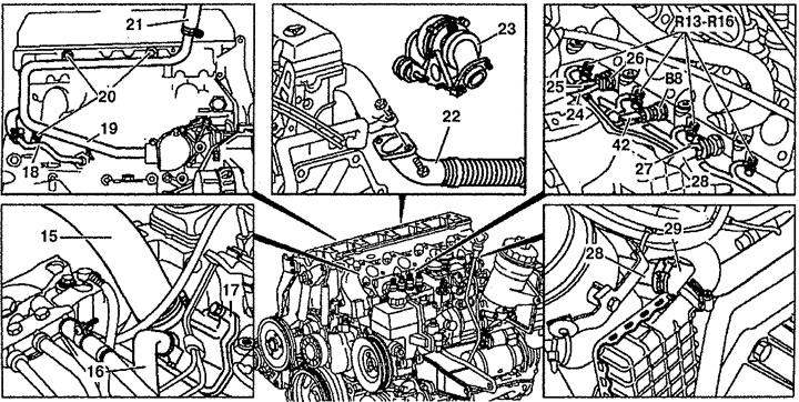
Pic. 4.16. Cylinder head:
15, 16, 29. Branch pipes of the cooling system,
17. Housing,
18. Discharge pipe of the heating system,
19. Return pipe of the heating system,
20. Bolts,
21. Pipe of the cooling system,
22. The front of the exhaust system,
23. Turbocharging,
24, 25. Vacuum tubes,
26. Thermal valve,
27. Protector,
28. Cooling system pipe,
AT 8. coolant temperature sensor,
R13-R16. glow plugs,
X42. Coolant temperature sensor wiring connector.
15. Disconnect vacuum tubes 24 and 25 from thermal valve 26.
16. Disconnect the X42 wiring connector from the coolant temperature sensor B8.
17. Disconnect the pipes of the cooling system 15 and 16 from the housing 17.
18. Disconnect the branch pipe of the cooling system 29 from the pipe of the cooling system.
19. Remove the protectors 27 and the cooling system pipe 28.
20. Remove the cooling system pipe 21 from the heating system return pipe 19.
21. Remove bolts 20.
22. Disconnect the heating system return pipe 19 from the cooling system pump housing.
23. Disconnect the exhaust pipe 22 from the exhaust manifold.
24. Remove the turbocharger 23.
25. Unscrew the bolts 31 securing the timing chain cover.
26. Loosen and unscrew the bolts 32, 33 and 34 securing the cylinder head (see fig.4.17). The procedure for loosening the fastening bolts is shown in fig. 4.18.
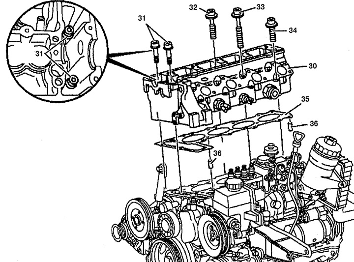
Pic. 4.17. Cylinder head:
30. Cylinder head,
31. Bolt,
32, 33, 34. Cylinder head bolts,
35. Cylinder head gasket,
36. Adjusting fingers.
Pic. 4.18. Procedure for loosening the cylinder head bolts
27. Check up bolts of fastening of a head of the block of cylinders and, if necessary, replace them.
28. Remove the cylinder head 30. Wipe the contact and threaded surfaces, check for damage.
Installation
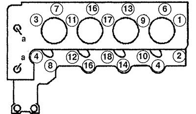
29. Installation is made in an order, the return to removal. Replace the cylinder head gasket 35 and make sure it is properly seated on the adjusting pins 36. The order of an inhaling of bolts of fastening of a head of the block of cylinders is specified on fig. 4.19.
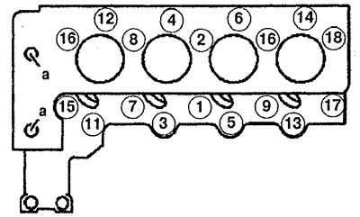
Pic. 4.19. The order of tightening the cylinder head bolts
30. Grease a carving part and a basic surface of a head of the block of cylinders.
31. Replace the retainer for the return pipe of the heating system 19.
32. Spring 2 is installed with a colored mark up.