



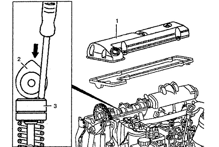
Figure 4.27a. Checking the hydraulic compensator:
1. Cylinder head cover,
2. Cam,
3. Hydraulic compensator.
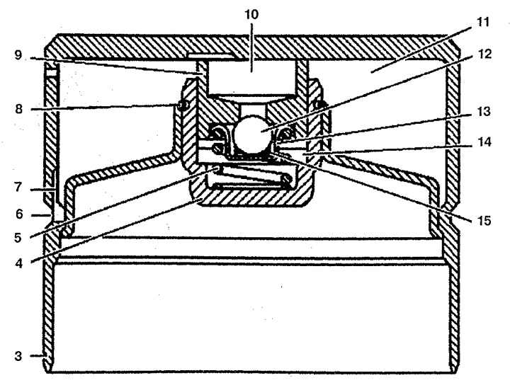
Figure 4.27b. Checking the hydraulic compensator:
4. Guide glass,
5, 15. Spring,
6, 7. Oil channel,
8. Locking ring,
9. Bolt,
10, 11. Oil cavity,
12. Ball valve,
13. Ball valve guide,
14. Working chamber.
2. Rotate the camshaft until cam 2 of the desired valve is directed with the conical part upwards.
3. Check the hydraulic compensator by pressing it with a rod using normal force by hand. Do not use a metal rod. If one of the hydraulic lifters drops faster than the others, it must be replaced.