Contents: Removal ↡ Installation ↡
Removal
1. Remove the air filter.
2. Remove the cylinder head cover 1 (see figure 4.21).
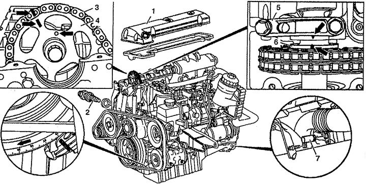
Figure 4.21. Camshaft:
1. Cylinder head cover,
2. Chain tensioner,
3. Timing chain,
4. Camshaft pulley,
5. Bearing cover,
6. Camshaft,
7. Locking device.
3. Set the piston of the first cylinder to TDC. The marks on the camshaft and the first bearing cap must be aligned.
4. Mark the location of the timing chain 7 on the camshaft pulley 4 (arrows).
5. Install the locking device 7 on the flywheel ring.
6. Remove chain tensioner 2.
7. Unscrew bolt 12, remove gasket 13 and camshaft pulley 4 (see figure 4.22).
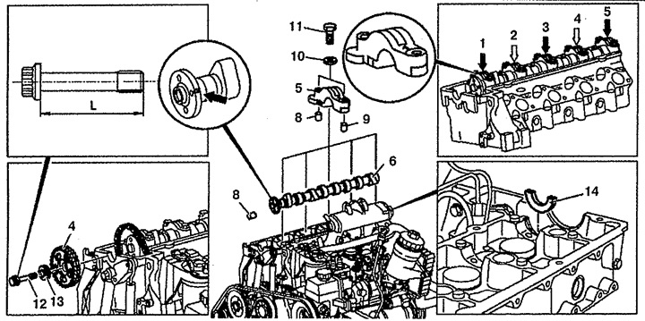
Figure 4.22. Camshaft:
4. Camshaft pulley,
5. Bearing cover,
6. Camshaft,
8. Cylindrical finger,
9. Adjusting bushings,
10. Gasket,
11, 12. Bolt,
13. Gasket,
14. Radial runout regulator.
8. Loosen the 5 main bearing cap of the camshaft and remove it. The order of loosening the bolts for fastening the camshaft main bearing caps is shown in the figure 4.23. First, you need to unscrew the bolts that secure the 1, 3, and 5 caps. Then you need to unscrew the bolts that secure the 2 and 4 caps. The camshaft bearing caps are marked with the bearing number (see figure 4.24).
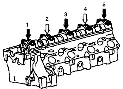
Figure 4.23. The order of loosening and tightening the bolts securing the camshaft bearing caps.
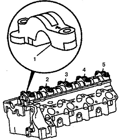
Figure 4.24. Marking of camshaft bearing caps.
9. Remove camshaft 6. Check radial runout adjuster 14 of the camshaft.
Installation
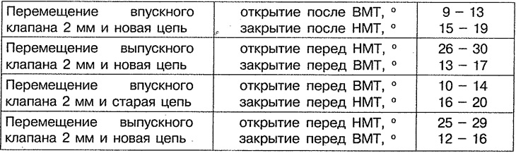
10. Installation is carried out in the reverse order of removal. Lubricate camshaft 6 and install it in the cylinder head so that the TDC mark on the camshaft (arrow) is facing upwards (see figure 4.22). The mark on the timing chain 3 must be aligned with the mark on the camshaft pulley 4. Before installing the cylinder head cover, make sure that the TDC mark on the camshaft and its pulley 4 coincides with the mark on the timing chain 3. Tighten the camshaft bearing cap bolts in the reverse order of loosening. The engine valve timing phases are shown in Table 4.1.
Table 4.1. Engine valve timing.