
Cars BMW Cars Volkswagen Cars Chevrolet Cars Land Rover Cars Lada Cars Honda Cars Peugeot
English Русский
Български
Беларускі
Український
Српски
Hrvatski
Română
Polski
Slovenský
Magyar
Bookmark News and articles Sitemap Feedback Site search
MercedesMan.ru


A-Class C-Class E-Class G-Class M-Class S-Class Others
Sprinter (1995-2000, diesel) Vito 1 (1996-2003) Vito 2 (2003-2014, diesel) Vario 814D (1996-2003, diesel)
  • Main
  • Mercedes-Benz
  • Sprinter (1995-2000)
  • Transmission
  • Rear axle and cardan
  • Removal and installation the rear axle (for models without ABS)

Removal and installation the rear axle (for models without ABS) (Mercedes-Benz Sprinter 903)

0
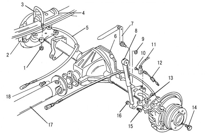
Figure 220. Rear axle of a vehicle without ABS: 1 — spring U-bolt nut, 100–120 N·m; 2 — spring; 3 -…

Figure 220. Rear axle of a vehicle without ABS: 1 — spring U-bolt nut, 100–120 N·m; 2 — spring; 3 - spring ladder; 4 - rubber stop pad; 5 — parking brake cable; 6 - rear axle; 7 — rear brake pressure regulator drive lever; 8 — shock absorber; 9 — nut, 30–35 N·m (always subject to replacement); 10 — bolt, 10 Nm (always subject to replacement); 11 — brake pad wear sensor wire connector; 12 — brake pad wear sensor wire; 13 — brake hose, 12–16 Nm; 14 — wheel mounting bolt, 160–180 N·m; 15 — shock absorber mounting bolt; 16 — nut, 75–85 N·m (always subject to replacement); 17 — cardan shaft; 18 — bolt, 75 Nm


The bridge mounting is shown in the figure 220.

To remove it, you will need a jack with sufficient lifting capacity. It is better to carry out the work with an assistant, since the bridge must be held when removed. Work on removing the rear axle is carried out as follows:
  • loosen the wheel bolts while the car is on the ground;
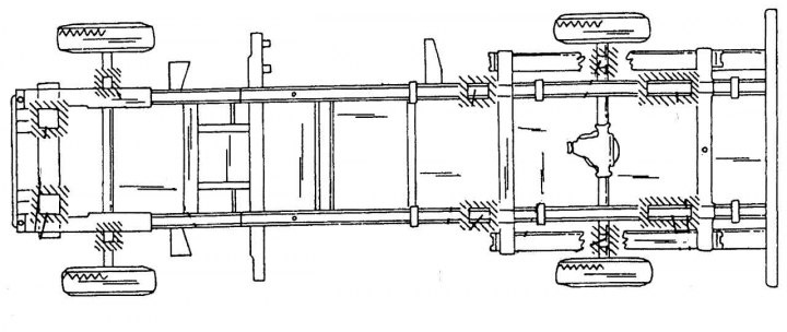
Figure 221. Recommended locations for installing vehicle supports (indicated by shading)

Figure 221. Recommended locations for installing vehicle supports (indicated by shading)


  • raise the rear of the car with a jack and install supports. In this case, it is better not to place them under the bridge itself. Figure 221 shows possible locations for support placement;
  • remove the brake pad wear sensor wire connector, unscrew the sensor and remove it;
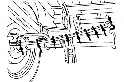
Figure 222. Fastening tape for removing the parking brake cable (must be removed before dismantling)

Figure 222. Fastening tape for removing the parking brake cable (must be removed before dismantling)

  • remove the one shown in the picture 222 fastening tape holding the parking brake cable;
  • remove the front parking brake cable from the equalizer lever, loosen the eccentric locking bolt in the middle of the lever, and unscrew the eccentric until the cables are free. For more details see. sec. "Brake system";
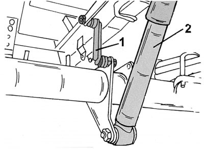
Figure 223. Fastening the pressure regulator lever (1) and shock absorber (2)

Figure 223. Fastening the pressure regulator lever (1) and shock absorber (2)


  • unscrew both shock absorbers from the rear axle. To do this, lift the bridge until the shock absorbers are unloaded (figure 223);
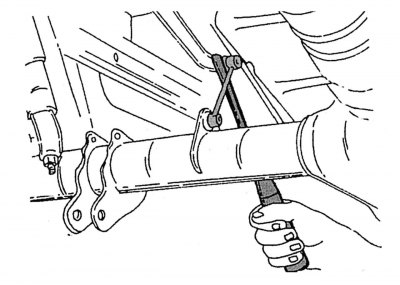
Figure 224. Disconnecting the pressure regulator lever

Figure 224. Disconnecting the pressure regulator lever

  • unscrew as shown in the picture 224, on the bottom side, above the bridge, the brake pressure regulator drive lever. Figure 223 also shows how the lever is attached;
  • disconnect the brake hose by holding the hose hex nut while loosening the brake line union nut. After this, remove the hose from the mount (remove tensioner). This work must be carried out on both sides. The ends of hoses and pipes must be properly sealed to prevent dirt from entering;
  • disconnect the propeller shaft from the rear axle flange. Be careful - the shaft may fall as soon as the last mounting bolt is unscrewed! Tie the shaft with wire;
  • unscrew the U-bolt nuts and remove the released pads. The assistant must hold the bridge, which is mounted on a jack;
  • slowly lower the bridge using the jack, then pull it out from under the car.

When installing the rear axle, the corresponding fastening parts shown in the figure 220, should be replaced.

During installation, you must perform the following operations:


  • install the bridge under the car, approximately in the middle between the springs;
  • raise the bridge to the attachment points. The center bolts of both springs must fit into the holes in the bridge. Raise the bridge until it rests against the springs;
  • install spring pads and U-bolts. If the ladders are not installed, they can be tightened by clamping them in a vice. Do not apply excessive force when installing the step ladders to avoid damaging the threads;
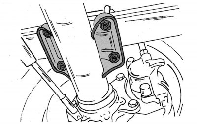
Figure 225. Dismantling the springs

Figure 225. Dismantling the springs

  • evenly tighten the U-bolt nuts crosswise and tighten to a torque of 100-120 N·m (figure 225);
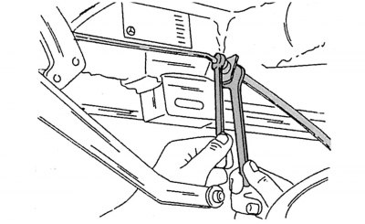
Figure 226. Disconnecting the flexible brake hose from the brake system pipeline

Figure 226. Disconnecting the flexible brake hose from the brake system pipeline

  • insert the brake hose into the pipeline, tighten the union nut to a torque of 12-16 N·m, holding the hose hex nut (figure 226);
  • secure the pressure regulator lever. Tighten the nut to a torque of 30-35 Nm;
  • tighten the shock absorber mounting nuts to the axle to a torque of 75-85 N·m;
  • connect the propeller shaft to the rear axle flange (75 Nm);
  • insert both parking brake cables into the guides and secure them with clamps on the back side. Secure the cable itself with fastening tape;
  • secure the cable to the equalizer lever. The parking brake should be adjusted as described in section. "Brake system";
  • bleed the brakes;
  • check the oil level in the rear axle housing if the work is completed;
  • install the wheels, lower the vehicle and tighten the wheel mounting bolts to 160–180 N·m.

Material taken from a web resource [MercedesMan.ru]
This article is available at: russian, bulgarian, belarusian, ukrainian, serbian, croatian, romanian, polish, slovak, hungarian
The article has been verified: Levin Kirill Glebovich
Share with friends:
◀ Previous
Mercedes Sprinter / Rear axle and cardan
Next ▶

Rear Axle and Propeller Shaft — General Description
Removal and installation the rear axle (for models with ABS)
Disassembling the rear axle
Removal and installation of drive axle shafts
Disassembling the drive axle shaft
Drive gear sleeve
More similar articles for repairing other models

☛ Rear window defroster Mercedes W168 (1997-2004)
☛ Rear view mirrors Mercedes W202 (1993-2000)
☛ Replacing the rear axle suspension bracket Mercedes W123 (1976-1985)
☛ Removal and installation of the rear axle assembly Mercedes W463 (1999-2019)
☛ Removal and installation of the rear axle assembly Mercedes W163 (1997-2005)
☛ Rear Axle — Design Description Mercedes W126 (1979-1991, petrol)
Link in different formats to this article
Comments and feedback from visitors
No comments yet


How much will 30 + 19 ?


Vario 814D (1996-2003, diesel) 
  • General information
  • Maintenance
  • Power unit
  • Engines 602.984/985
  • Engines 904.908/914/923/936
  • Transmission
  • Clutch
  • Manual gearbox 711.613
  • Manual gearbox 710.64/66
  • Manual gearbox 715.051
  • Automatic gearbox 723.345
  • Power take-off box
  • Chassis
  • Front suspension
  • Rear suspension
  • Steering
  • Brake system
  • Body and electrical equipment
  • Interior (internal elements)
  • Exterior (external elements)
  • Heater and air conditioner
  • Electrical diagrams
Vito 2 (2003-2014, diesel) 
  • General information
  • User manual
  • Maintenance
  • Diesel engine OM646
  • Engine repair
  • Cooling and lubrication system
  • Power and exhaust system
  • Transmission
  • Clutch
  • Car gearbox
  • Chassis
  • Front suspension
  • Rear suspension
  • Steering
  • Brake system
  • Body
  • Body elements
  • Electrical equipment
  • Equipment and devices
  • Security systems
  • Electrical circuits
Vito 1 (1996-2003) 
  • General information
  • User manual
  • Maintenance
  • Petrol engines 2.0 l
  • Engine repair
  • Lubrication system
  • Cooling system
  • Power and control system
  • Petrol engines 2.8 l
  • Engine repair
  • Lubrication system
  • Cooling system
  • Power and control system
  • Diesel engines 2.3 l
  • Engine repair
  • Cooling system
  • Lubrication system
  • Turbocharging and recycling
  • Power and control system
  • Diesel engines 2.2 l
  • Engine repair
  • Cooling system
  • Lubrication system
  • Turbocharging and recycling
  • Power and control system
  • Transmission
  • Clutch
  • Mechanical gearbox
  • Automatic gearbox
  • Chassis
  • Front suspension and wheels
  • Rear suspension
  • Steering
  • Brake system
  • Body
  • Exterior (external elements)
  • Interior (internal elements)
  • Electrical equipment
  • Equipment and devices
  • Heater and air conditioner
  • Electrical circuits
Sprinter (1995-2000, diesel) 
  • General information
  • Introduction to the guide
  • Maintenance
  • Power unit
  • Engine repair
  • Lubrication system
  • Cooling system
  • Power and exhaust system
  • Transmission
  • Clutch
  • Mechanical gearbox
  • Automatic gearbox
  • Front axle
  • Rear axle and cardan
  • Chassis
  • Car suspension
  • Steering
  • Brake system
  • Tires and wheels
  • Electrical equipment
  • Equipment and devices
  • Headlights and lighting
  • Power devices
  • Electrical circuits
 
MercedesMan.ru © 2017–2026 · Mobile version · Read about Mercedes · Sitemap: EN BG BY UA RS HR RO PL SK HU · Feedback · Site search · Bookmark A-Class (W168) · C-Class (W201) · C-Class (W202) · C-Class (W203) · E-Class (W123) · E-Class (W124) · E-Class (W210) · G-Class (W463) · M-Class (W163) · S-Class (W116, petrol) · S-Class (W126, petrol) · S-Class (W140) · S-Class (W220) · Sprinter · Vito 1 · Vito 2 · Vario 814D ·
 
We only use cookies without which some of the site's features may not be available.