
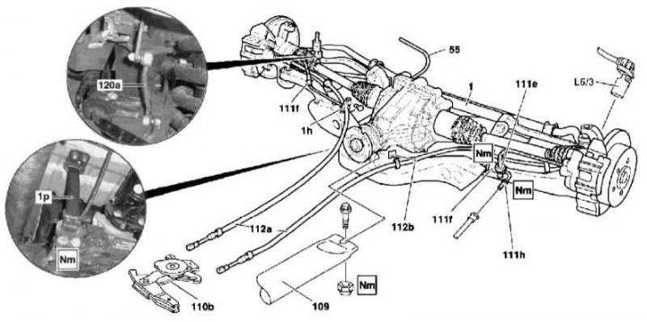
Rear axle assembly installation details
1 - Subframe; 1h - Parking brake cable support bracket; 1p - Control link; 55 - Rear differential crankcase ventilation hose; 109 - Longitudinal bracket for fastening the fuel tank; 110b - Compensation assembly of the parking brake actuator (slack adjuster); 111e - Brake hose; 111f - Brake hose/cable support bracket; 111h - Brake line; 112a - Parking brake cables; 112b - Parking brake cable support bracket; 120a - Rod of the landing level regulator; L6 / 3 - Left rear wheel sensor
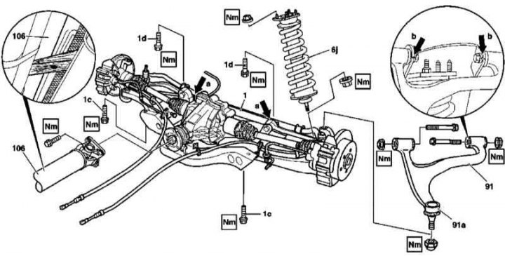
Rear axle assembly installation details
1 - Subframe; 1s - Bolts; 1d - Bolts; 6j - Rack assembly; 91 - Upper wishbone; 91a - Upper ball joint; 106 - Cardan shaft; a - Guide pin; b - Landing marks on the stringer
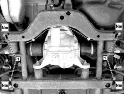
Rear suspension subframe installation details
1 - Mounting bolts
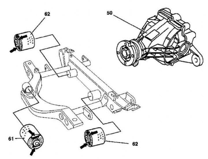
Location diagram on the support subframe (61, 62) differential suspension (50)
Note. All self-locking bolts and nuts must be replaced without fail!
1. Details of the installation of the rear axle assembly are shown in the illustrations, which include all references in the text.
2. Remove rear wheels.
3. On models 163.174 (ML 55 AMG) empty the fuel tank (see chapter Emptying the fuel tank), tie the additional tank to the longitudinal beam.
4. Disconnect the brake line (111h) from flexible hose (111e).
5. Remove the brake hose/cable support brackets (111f) from the longitudinal beams of the frame.
6. Remove wheel sensors (L6/3, L6/2).
7. If equipped, remove the rear axle from the subframe (1) exhaust system shield.
8. In the right front part of the shield, unbolt the parking brake cable support bracket (1h).
9. Release the rear differential crankcase ventilation hose (55) from the latch on the fuel tank, - except models 163.174 (ML 55 AMG).
10. Loosen the nut of the bolt of fastening to the subframe of the longitudinal bracket of fastening of the fuel tank (109).
11. Disconnect the rear parking brake cables (112a) from the regulator (110b) (see chapter Brake and auxiliary systems).
12. Release the cable assemblies (112a) from intermediate clamps on the frame.
13. Remove cable assembly support bracket (112b), installed on the left side of the floor panel.
14. Disconnect from the rear differential and tie the cardan shaft to the frame (106).
15. Detach from subframe (1) control ligament (1r).
16. On models equipped with xenon headlights, disconnect the landing level control rod from the upper support (120a).
17. Remove the rack assembly from the lower transverse arm (6j).
18. Squeeze out the upper ball joint from the hub assembly (91a).
19. Support the rear differential assembly - use the special tool.
20. Remove bolts (1c and 1d) subframe mountings and carefully lower the rear axle assembly, taking care not to pinch the brake cables and tubes.
Note. On models 163.174 (ML 55 AMG) first lower the axle assembly and release the differential ventilation hose (55) from the latch on the wall of the additional fuel tank.
21. Inspect assembly components for signs of damage, replace failed parts.
22. If necessary, disconnect from the longitudinal beams and remove the rack assemblies (6j) or upper wishbones (91).
23. Also, if necessary, remove the subframe and replace the rubber pads of the differential suspension mounts; the bushings are removed / installed using a special extractor.
24. Installation is carried out in the reverse order - before installation, carefully clean the bridge mating surfaces (1) and longitudinal beams, if necessary, eliminate the deformation of the surfaces, also drive the bolt holes in the floor panel under the subframe mounting bolts with a tap (1c and 1d). Make sure the guide pins (A) fell into the receiving holes in the beams. Final tightening of the transverse arm fasteners (if filmed) is carried out only after the car is lowered to the ground, - when installing, make sure that the axle assembly is in a strictly horizontal position, take care of the correct alignment of the landing marks on the beams (b). Do not forget about the need to replace the sealing elements of the nipple connectors of the hydraulic lines.
25. In conclusion, correct the level of the working fluid and pump the brake path (see chapter Brake and auxiliary systems), check the oil level in the differential.
26. Correct the direction of the optical axes of the headlights and adjust the geometry of the suspension (see part suspension geometry).