
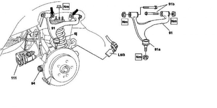
Details of installation of the upper transverse arm of the rear suspension
6j - Rack assembly; 91 - Upper wishbone; 91a - Upper ball joint; 91b - Axial bolts; 111 - Brake caliper (do not disassemble); L6 / 3 - Left rear wheel sensor; Arrows - Landing marking of bolts of fastening of the lever on a lateral beam of a frame
Note. All self-locking bolts and nuts must be replaced without fail!
1. The installation details of the lower transverse arm of the rear suspension are shown in the illustration, to which all references in the text refer.
2. Remove the rear wheels, remove the spare tire (except for models with the latter mounted on a holder behind the tailgate and models 163.174). If equipped, remove the outer spare wheel holder.
3. On models 163.174 (ML 55 AMG) remove the wheel arch protectors.
4. Remove wheel sensor (L6/3, - in case of left lever).
5. Detach the rack assembly (6j) from the side suspension beam (see Section Removal, disassembly and installation of rear racks).
6. Press out the upper ball joint (91a) from the hub assembly.
7. Disconnect the lower transverse arm from the subframe (see Section Removal, disassembly and installation of rear racks).
8. Give the fixing nuts, having previously marked the installation positions (arrows), remove the axle bolts (91b) and separate the upper arm (91) from the frame beam.
9. Check the condition of the rubber axle bushings and ball joint, replace if necessary (see Sections Removal and installation of the lower transverse arm, replacement of the front axle bushing and Check of a condition of spherical support of a rotary fist).
10. Installation is carried out in the reverse order - when installing the levers, the bridge assembly must occupy a strictly horizontal position. Follow the correct alignment of the landing marks applied during dismantling (arrows).