



Note: All self-locking bolts and nuts must be replaced!
Removal
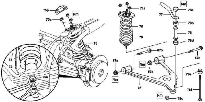
Rear Suspension Strut Assembly Installation Details
67 - Lower wishbone; 67a - Nuts; 67b - Bolts; 73 - Coil spring; 75 - Telescopic shock absorber; 75a - Nuts; 75u - Nut; 75r - Lid; 77 - Torsion bar; 78 - Spacer sleeve; 78a - Bearing with nut; 78b - Bearing; 78d - Bearing; 78e - Bearing; 78f - Connecting bolt
1. The details of the rear suspension strut assembly installation are shown in the illustration, to which all references in the text refer.
2. Remove the rear wheels, remove the spare tire (except for models with the latter fastening on the holder behind the tailgate and models 163.174). If equipped, remove the outer spare wheel carrier.
3. On models 163.174 (ML 55 AMG), remove the wheel arch protection liners.
4. Remove the cover (75r).
5. Loosen the nuts (75a) securing the rack assembly to the side frame beam.
6. Having locked the threaded rod from turning, loosen the nut (75u) of the lower shock absorber support (75) on the lower suspension arm (67).
7. Support the lower wishbone (67).
8. Loosen the nut and remove the connecting bolt (78f) securing the torsion bar (77) to the lower arm (67).
9. After loosening the nuts of the mounting bolts, disconnect the lever (67) from the subframe and carefully lower it down, removing it from the guide.
10. Release the shock absorber (75) rod from the lever (67) of the threaded shock absorber - if necessary, use a soft-faced hammer.
Disassembly
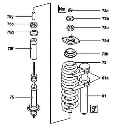
Rear suspension strut assembly design
73 - Coil spring; 73a - Nut; 73b - Washer; 73c - Upper cushion; 73d - Thrust bearing; 73h - Spring guide; 75 - Shock absorber; 75c - Bottom cushion; 75f - Lid; 75g - Washer; 75y - Bushing; 01 - Coil Spring Compressor Tool; 01a - Captures
1. The installation details of the rear suspension strut assembly components are shown in the illustration to which all references in the text refer.
2. After compressing the coil spring using a special tool (01, 01a), remove the shock absorber (75).
3. Release the spring compression tool.
4. Assess the condition of the upper components of the shock absorber; replace any faulty parts.
Article based on data from the website Mercedesman.ru
Attention! Also make sure that the washer (75g) is installed correctly.
5. Carefully examine the condition of the shock absorber piston rod - if deformations or signs of a violation of the smoothness of the piston movement are detected, the shock absorber must be replaced.
6. Check for signs of external leaks developing.
7. Replace the defective shock absorber, preferably in a set with the second one.
8. Assemble the rack assembly - the spring compression is again performed using a special device.
Installation
Installation is performed in the reverse order of component dismantling. When installing the transverse arm, the rear axle must be in a strictly horizontal position. Ensure that the cover is seated correctly (75p).