
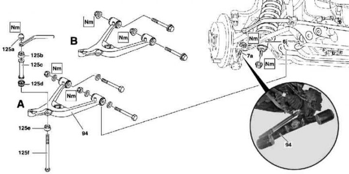
Details of installation of the lower transverse arm of the rear suspension
6j - Rack assembly; 7a - Lower ball joint; 94 - Lower wishbone; 125a - Bearing with nut; 125b - Bearing; 125 - Remote sleeve; 125d - Bearing; 125e - Bearing; 125f - Bolt; A - Version 1; B - Version 2
Note. All self-locking bolts and nuts must be replaced without fail!
1. The installation details of the lower transverse arm of the rear suspension are shown in the illustration, to which all references in the text refer.
2. Remove rear wheels.
3. Detach the rack assembly (6j) from the lower transverse arm (94).
4. Remove bearing with nut (125a) and remove from the lever (94) bolt (125f).
5. Give the fixing nuts, remove the axle bolts, separate the lever (94) from the subframe and swing it down on the ball joint (7a).
6. If necessary, while holding the ball head with a TORX key, release the support (7a) from the lever (94).
7. Remove the lower transverse arm (94).
8. Assess the condition of the ball joint (7a) (see Section Check of a condition of spherical support of a rotary fist), if necessary, remove the support (use the extractor) and replace it.
9. Installation is carried out in the reverse order - make sure that when landing the lever and tightening the bearing with the nut (125a) the rear axle assembly was located strictly horizontally.