
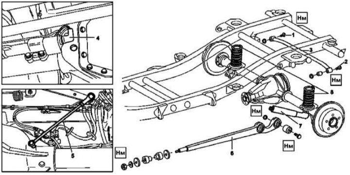
Rear axle assembly installation details
1, 2 - Bolts for fastening the diagonal rod to the bridge and frame; 3 - Diagonal bar; 4 - Wiring connector; 5 - Thrust (only on models without EBV); 6 - Trailing arm; 7 - shock absorber; 8 - Helical spring
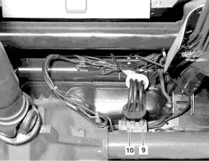
Wiring diagram for hydraulic lines for brake drive and rear differential lock
9 - Holder
10 - Hydraulic line
Removing
1. Drain the oil from the rear differential (see chapter Ongoing care and maintenance).
2. Separate the cardan shaft from the final drive gear connecting flange and tie it to the frame.
3. Give nuts of fastening of the bottom support of shock-absorbers (7).
4. Relax (but don't twist) bolts (1 and 2) diagonal bar attachment (3) to the rear axle and to the frame.
5. Disconnect and plug the tucked into the holder (9) brake lines, as well as a hydraulic line (10) rear differential lock actuator.
6. Disconnect the connector (4) electrical wiring on the slave cylinder of the rear differential lock actuator.
7. Having disconnected from the body side, remove the rear ABS wheel sensors (see chapter Brake and auxiliary systems).
8. Connect the wiring of the sensors from the side of the bridge.
9. Disconnect from the lever and remove, passing through the floor panels, the parking brake cables (see chapter Brake and auxiliary systems).
10. On models not equipped with brake force distribution (EBV) disconnect the rod (5) automatic brake pressure regulator.
11. Release the parking brake cables from the intermediate clamps on the trailing arms (6).
12. Hang the car so that you can remove the coil springs (8) (see Section Removal and installation of front suspension springs).
13. Turn out a bolt (1) diagonal bar attachment (3), then pull the axle assembly back and out from under the vehicle.
14. Unbolt the trailing arms from the bridge (6).
Installation
1. Bolt trailing arms to axle (6).
2. Behind get assembly of the bridge under the car.
3. Install springs (8) (see Section Removal and installation of front suspension springs).
4. Screw (but don't over tighten) bolt (1) diagonal bar attachment (3).
5. Lower the car so that the trailing arms can be seated (6) into the frame.
6. Having placed rubber bushings of levers on the frame (6), tighten the fixing nuts.
7. Fix in the clamps on the levers (6) parking brake cables.
8. Reinstall shock absorbers (7) (see Section Removing, checking and installing rear shock absorbers).
9. Tighten the bolts (1 and 2) diagonal stay attachments (3).
10. Install brake lines and rear differential lock actuator hydraulic line.
11. Connect the electrical wiring to the ABS wheel sensors and install the latter in their regular places.
12. Connect the electrical wiring (4) to the differential lock slave cylinder.
13. On models without EBV, install the linkage (5).
14. Connect the parking brake cables.
15. Connect the cardan shaft.
16. Fill oil into the gearbox housing (see chapter Ongoing care and maintenance).
17. Finally, bleed the brake system and differential lock drive (see chapters transmission line and Brake and auxiliary systems).
18. Adjust parking brake actuator (see chapter Brake and auxiliary systems).