
Check necks (pins) supports for deviation from a steep shape and for narrowing.
Clamp the crankshaft between the two projections of the rotary machine or insert it into two prisms and measure the runout of the camshaft using a dial gauge.
Main and connecting rod bearing clearance can be measured with a calibrated plastic feeler gauge. Place a plastic feeler gauge over the entire length of the bearing journal and install the bushing together with the bearing cover. Tighten the bearing cover bolts to the required torque.
Detach the cap and insert again and then determine the thickness of the plastic feeler gauge. Before buying new liners for main and connecting rod bearings, you need to determine how much the main and connecting rod journals of the crankshaft will be ground.
Measure axial (axial) crankshaft clearance. The measured backlash must be within the required limits.

The ball bearing for the journal of the input shaft of the gearbox must be replaced when repairing the engine.
The bearing and the plug ring must be pulled out together using a puller and stop.
Lubricate the new bearing and, using a suitable rod, fit onto the crankshaft..
Drive in the ring plug.
V8 crankshaft and related parts
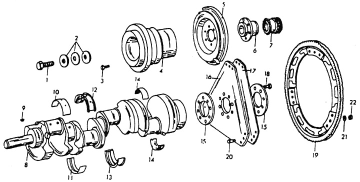
1. Bolt M18x1.5x45 mm. 2. Flat springs (3 pcs.). 3. Bolt M8x22 mi (6 items). 4. Pulley. 5. Vibration damper. 6. Hub. 7. Crankshaft gear. 8. Crankshaft. 9. Key. 10. crankshaft bearing shell in the cylinder block. 11. Crankshaft bearing shell in bearing cap. 12. Insert of the central bearing in the block of cylinders. 13. Insert of the central bearing in a bearing cover. 14. Insert connecting rod bearings. 15. Washers 4.5 nm thick. 16. Transmission (slave) disc 1.5 mm thick and 286 mm in diameter. 17. Transmission (slave) disc 1 mm thick and 287 mm in diameter. 18. Coupling bolt for transfer discs M12x1.5x23 mm (8 pieces). 19. Crown with a welded steel ring. 20. Central bolts. 21. Spring washer B6. 22. Nut M6.
Flywheel
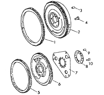
1. Starter drive ring gear. 2. Flywheel. 3. Mounting pin. 4. Flywheel mounting bolt. 5. Starter drive ring gear. 6. Flywheel for automatic transmission. 7. Drive disc. 8. Distance washer. 9. Mounting pin, 10. Bolt for fastening drive disks.
The installation of the flywheel has already been described above. When reusing an old flywheel the plane should be checked for scratches and wear.
If a new flywheel is installed, it must be the same weight as the old one.
Intermediate flange
If an intermediate flange is installed, it must be centered.
Insert the intermediate flange into the central pins on the cylinder block and lightly tighten the mounting bolts.
Attach a dial indicator to the crankshaft and place its feeler gauge on the outer diameter of the round center portion of the intermediate flange.
Rotate the crankshaft and measure the highest runout. When turning the crankshaft, make sure that the dial indicator gauge does not hang in the recess in the intermediate flange.
Use light taps on the intermediate flange to correct the runout. If it is too large, then remove the intermediate flange, drill both holes for the central pins to a diameter of 12.1 to 12.2 mm, install thicker pins and repeat the measurement.