
Loosen the clutch mounting bolts evenly and remove the clutch.
Remove alternator, ignition distributor and starter.
Remove fan with coolant pump.
Remove thermostat housing.
Remove the right and left engine mounts. '
Remove the oil filter and pipes along with the fuel pump.
Pull out the dipstick and its tube.
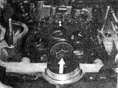
Remove the carburetor, fuel lines, fuel metering unit with air metering, intake and exhaust manifolds. a Crank the engine and put it in the TDC position.
Remove cover (lids) cylinder heads.
Mark the relative position of the camshaft gear and drive chain with paint or something similar.
Loosen the spacer bolts of the camshaft gears by holding the camshaft with a suitable wrench.
Remove gears.
Remove chain tensioner.
Remove the inner chain guide rails by pulling out the support pins with a hammer puller and then removing the chain guide rails.
Loosen and then unscrew the cylinder head bolts in the reverse order shown in the tightening diagram.
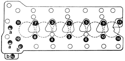
Tightening sequence for cylinder head bolts on M110 engines (280S/280SE)
Remove cylinder heads. To raise the right head, push the tensioner with the chain towards the middle of the engine so that the tensioner does not remain hanging.
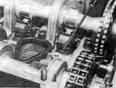
For M110 engines (280SE) for removing gears (stars) camshaft, both covers on the camshaft housing must be unscrewed from the front.
Press out the rocker arm tension springs and remove all rocker arms. To do this, use either a large screwdriver or a puller (N 110 589 046 100).
Remove the upper bearings in the camshaft housing.
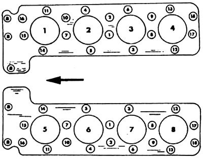
Tightening sequence for cylinder head bolts on V-8 engines A. Bolts M8
Press back both camshafts and remove the gears (gear wheels) camshafts.
Remove the guide sprocket by knocking out the support pin using the impact extractor 116 589 203 300.
Remove the chain guide bar in the cylinder head. To do this, knock out the support pins with an impact puller.
Remove the cylinder head gasket.
Turn the engine over on the mounting stand or, if it is not available, put it on a plane to mount the block head. Be careful not to damage the surfaces.
Remove the oil pan.
Unscrew the bolts securing the oil pump to the crankcase and to the bearing cap and pull out the oil pump. For V8 engines, after unscrewing the oil pump mounting bolts, loosen the bolt on the gear wheel (asterisk) oil pump circuits. Tilt the oil pump back and remove the bolt.
Use a screwdriver to move the chain sprocket off the oil pump and disconnect it from the chain. Then remove the pump.
Remove the damper bar in the crankcase after removing the drive mechanism cover (front cover).
Remove the tension bracket for the oil pump drive chain after removing the guard.
Remove the intermediate gear to drive the ignition distributor.
If necessary, remove the support sleeve in the crankcase housing and in the front cover.
Remove guide sprocket.
Remove drive chain.
At the M110 engine (280SE) remove the helical gear shaft, for which knock out the cover with the help of an impact puller and pull up the helical gear shaft with the Mb bolt.
Remove vibration damper and pulley.
Unscrew the plug bolt in the crankcase and remove the oil pressure relief valve.
Remove the ignition distributor housing and remove the clamp.
Loosen the intermediate gear bolt (asterisks).
Unscrew the chain guard. Drive the idler shaft inward while pulling the idler gear forward. Loosen the mounting screw of the support sleeve and pull out the intermediate gear shaft together with the support sleeve using the M8 screw. If necessary, pull out the rear support sleeve using a puller with an internal lug.
Remove the connecting rod bearing bolt nuts. Mark bearing cover and remove together with lower bearing shell.
Position the engine so that the pistons and connecting rods can be moved with a hammer handle from the cylinder bore. On light metal V8 engines, take care not to damage the bores. You can use tool N 117 589 009 800 for connecting rods and connecting rod bolts. All associated parts must be marked so that they can then be installed again in their original position.
Place a piece of hard wood between the crankshaft shoulder and the crankcase to secure the crankshaft and unscrew the flywheel from the crankshaft flange. Turn out the crankshaft bolts from the front, g Mark the relative position of the crankshaft and the hub with a center punch or chisel so that the hub groove is aligned with the disc spring during assembly.
Pull out vibration damper with pulley and bushing by hand. If necessary, you can use a plastic hammer, but remember that the cast iron pulley is sensitive to shock.
On a 6-cylinder engine, the balancing disc must be removed with puller N 116 589 103 300.
On vehicles with automatic transmission, unscrew the transfer plate extension bolts and remove them together with the toothed rim in the same way as the spacer plates.
Mark all main bearing caps and remove their bolts from the crankcase.
Carefully lift the crankshaft over the upper bearings. Remove the lower bearing shells.
Carefully remove piston rings with a piston ring extractor. Remove the piston pin retainers and pull out the piston pins. Arrange all the details in the correct order.
Remove drive chain.
Remove the plug screw and unscrew the oil pressure relief valve from the main oil line.
Knock out the back cover (steel ball) with steel rod (13 mm in diameter and about 700 mm long) from the front of the engine.