
Rotate the engine on a bench or workbench so that the side of the oil pan is facing up.
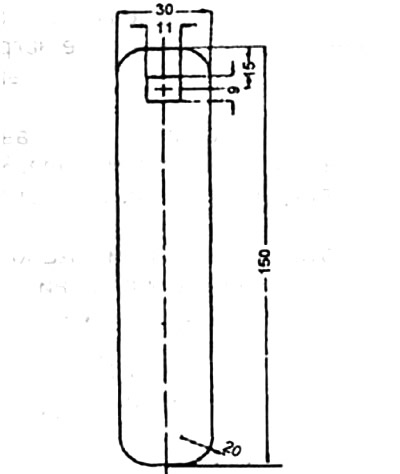
After all oil passages have been cleaned, drive a steel ball with a curling rod into the oil passage from behind.
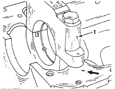
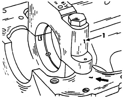
Screw in the oil pressure relief valve and tighten the plug screw.
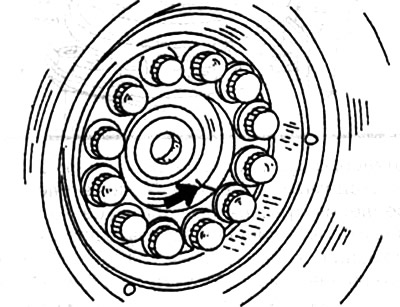
Insert the main bearing shells in a row into the holes for them in the engine crankcase. The upper bearing shells of V8 engines are equipped with a lubrication groove, while in 6-cylinder engines the upper and lower bearings, with the exception of the 4th bearing, are equipped with a lubrication groove, and the upper shell of the fourth bearing has one oil hole at its ends and one recess for oil.
Bearing shells are supplied ready to install for various repairs and should only be replaced as a complete set. The central bearing is supplied in case of refurbishment with an increased width and must, in order to obtain a running layer on the flywheel side, only be reworked on the unloaded side at right angles to the bearing bore.
The liners, in general, can be replaced with each other when they are new. The same applies to inner liners.
Install the main bearing caps in a row, checking their designation, and tighten their bolts to the required torque.
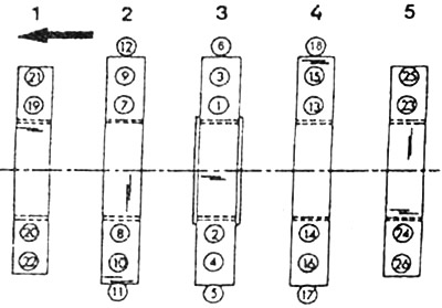
Crankshaft liners on 8-cylinder V-engine
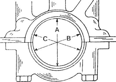
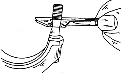
Measure the main hole in directions A, B and C in two planes. For a main bore that is larger than required or is tapered, machine the bearing cap on the bearing surface on a lapping surface and remove a maximum of 0.02 mm. The crankshaft bearing caps on V8 engines are machined with the engine block and are not available as spare parts.
Install the crankshaft bearing shells and tighten the bearing cap again to the required torque.
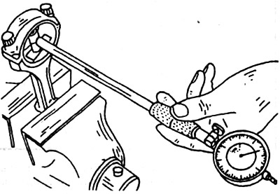
Measure the bearing diameter and check the radial clearance (backlash). It can be corrected by replacing the liners, while the average value of the specified bearing clearance must be achieved.
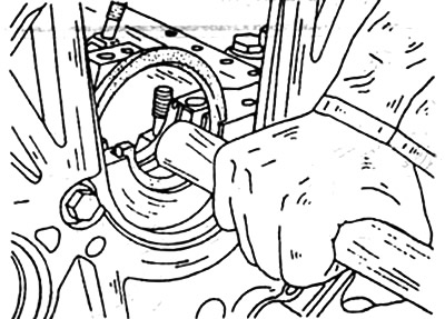
Insert a new radial o-ring into the engine crankcase at the rear and seat it firmly with a wooden hammer handle.
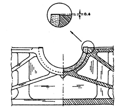
To achieve the required overlap, the radial seal ring must be cut 0.5 mm above the interface. For cutting, you can use a template 0.6 - thickness, which you can make yourself.
Lubricate the radial o-ring, bushings and crankshaft with SAE30 engine oil and install the crankshaft for driving purposes.
For V8 engines, lubricate the rear cover with sealant and tighten it. Fill the radial sealing ring between boot and dust seal with long-life grease and press it into the cover as far as it will go. To do this, it is better to use special tool 117 589 004 300. If this tool is not available, first press the sealing ring into the cover and then tighten the rear cover.
Tighten the crankshaft bearing caps to the correct torque. On V8 engines, self-locking bolts with pins are screwed into the cylinder block to fasten the crankshaft bearing caps. These bolts should only be screwed in once, as when they are turned away, the fixing effect disappears.
The outer bolts with pins are located 2mm from the middle, so the bearing cover can only be mounted in one position. When repairing, it is not allowed to use screw nozzles for self-locking bolts with pins of the crankshaft bearing caps.
Tighten the crankshaft bearing cap bolts to the correct torque in the correct sequence.
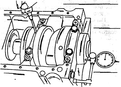
Measure axial (axial) crankshaft play.
Turn the crankshaft by hand and check if it rotates freely. If it rotates heavily, then correct its position by moving the bearing shells with a plastic hammer.
Install the intermediate gear for driving the ignition distributor and the end gear.
Install the helical gear shaft to drive the oil pump.
If the gear (star) crankshaft or intermediate gear with bushings were replaced with new ones, then the misalignment should be measured. To do this, measure the distance from the front side of the cylinder block to the intermediate gear and then to the crankshaft gear. The difference between these values should not be more than 0.1 mm. If the deviation is greater, the compensating element must be replaced (leveling) ring behind the crankshaft wheel.
Attach the flywheel or transfer disc to the crankshaft flange. The flywheel is marked with the crankshaft. If a new flywheel is installed, it must be the same size and weight as the old one.
Measure the bolt extension diameter. If the minimum diameter is reached, then the bolts must be replaced with new ones;
Screw in the bolts and tighten them to the required torque and to the desired angle, and tighten the bolts further by an angle of 90°+ 10°.
For V8 engines, when installing, pay attention to the sequence in which the transfer discs are installed.
Transfer discs can only be installed in one position, as one of the eight fastening bolts is located with an offset relative to the mounting circle along the centers of the holes. Therefore, the transfer discs must be in one specific position and the holes must match exactly. The ring gear is welded to the steel ring and a bolt is also attached to the transmission disc. When removing the gearbox (checkpoint) the ring gear remains on the engine.
Check the condition of the connecting rod bolts, bushings and turn the connecting rod.
Install the connecting rod bearing cap and tighten the connecting rod bolts.
Measure the main hole.
Install the connecting rod bearing caps with bearing shells and tighten the connecting rod bolts.
Measure bearing diameter and radial play. The bearing play can be corrected by changing the bearing shells, whereby the average allowable play must be achieved.
Lubricate the connecting rod bushings and piston pins with oil and insert them by hand.
Insert the piston pin retainer into the groove. Position the pistons on the connecting rod so that the arrow points in the direction of travel and the groove for the retaining lug of the bearing shell points to the left side in the direction of travel or, on V8 engines, to the outside of the engine.
When installing pistons that have already been used, check the piston rings for lateral and axial clearance. Do not heat the pistons and do not replace the piston pins of individual cylinders.
Insert the piston rings into the grooves on the pistons and check for ease of movement. Distribute the ends of the piston rings evenly over the circumference of the piston.
Lubricate the connecting rod bearing shells and pistons with SAE30 engine oil.
Use piston ring compressor 000 589 2061 00 or tightening band 000 589 041 400 and insert the pistons so that the arrow points in the direction of travel without applying force. For V8 engines, cover the connecting rods with a protective cover so as not to damage the cylinder walls.
Place the connecting rod bearing caps on the connecting rods in accordance with the numbers one after the other and tighten the connecting rod bearing bolts.
Turn the crankshaft and check for ease of movement between the connecting rod and the piston bore.
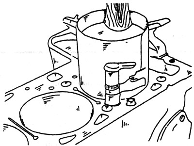
At TDC position of the pistons/measure the distance between the bottom of the piston and the interface plane of the cylinder block.
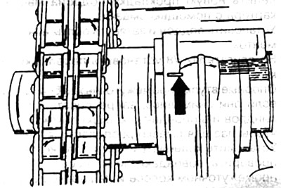
Install the oil pump. On V8 engines, hang the gear wheel on the chain and slide the oil pump onto the wheel. The tension sleeve in the gear must be inserted into the recess on the drive shaft. Tilt the oil pump back, install and tighten the gear wheel bolt. Attach the oil pump with bolts. When tightening the bolt, keep the chain tensioner spring from rotating with a screwdriver.
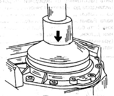
Drive a new spacer ring onto the crankshaft stub.
Lubricate the edges of the new radial sealing ring with oil and insert the ring into the clamping hole in the block body.
On 6-cylinder engines, insert a new radial seal into the oil sump.
Install damper bars.
Lightly lubricate the upper surface of the cylinder block with grease, or stick a new oil pan gasket with grease.
Install the pan and tighten the bolts to the correct torque.
On V8 engines, install the front cover.
Press the idler gear bushings, if they were removed, into the cylinder block and into the front cover so that the lubrication groove is at the bottom. Set the crankshaft 8 to the TDC position and check whether the marks on the intermediate wheel and on the cylinder block match. otherwise- (the ignition distributor cannot be set to the correct position. Replace the rubber O-rings of the coolant passages and lubricate the sealing surface of the front cover with sealant before installation.
Install balance disc and pulley. The balancing disk on 6-cylinder engines is fixed on the crankshaft using two movable pins, on 8-cylinder engines - using a disk spring.
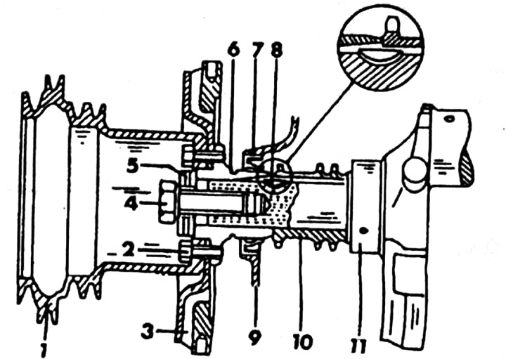
Cross section of the pulley, vibration damper, hub and transmission plate of V8 engines: 1. Pulley. 2. Bolt N8x22. 3. Vibration damper. 4. Bolt N18x1.5x45. 5. Disc washers (3 pieces). 6. Hub. 7. Radial sealing ring. 8. Disc spring. 10. Front cover, 10. Camshaft gear. 11. Crankshaft.
The vibration damper, pulley and hub on V8 engines must be bolted together in one specific position. One of the 6 holes is offset from the middle and therefore the holes must be exactly aligned with each other.
Turn the engine over and install the assembled cylinder head. Before doing this, check that the planes of the cylinder head and cylinder block are clean and free of foreign objects. In addition, you need to pay attention to the following:
- Do not use sealant on cylinder head gaskets or sealing surfaces.
- Rotate the crankshaft until the No. 1 piston is at TDC on the compression stroke, and install the camshafts as marked.
V8 engine
Engine 6-cylinder
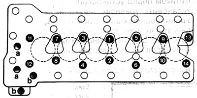
Tighten cylinder head bolts to specified torque. Tightening sequence:
Engine 6-cylinder
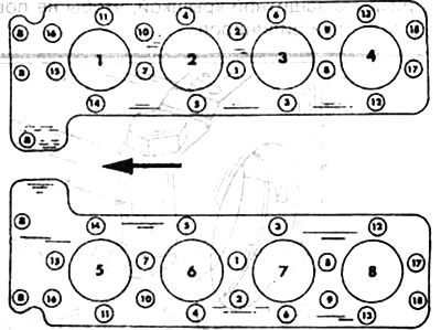
V8 engine
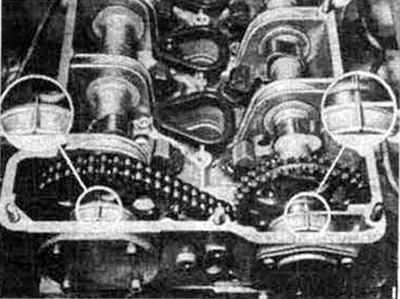
Raise the chain on the gear supports and place it on the camshaft gear.
Install the disc key on the camshaft, put on the equalizer disc and then install the gear and chain on the camshaft.
Put washers, spring washers on the mounting bolts and tighten the bolts.
Install the chain tensioner and tighten the mounting bolts evenly. On 6-cylinder engines, insert the chain tensioner housing into the cylinder head.
Screw in the threaded ring and tighten it to 50 Nm.
Install the pressure rod together with the installed stop and pressure springs into the housing and tighten the oil jet to 25 Nm. In this case, the pressure rod should jump forward with an audible click. Screw in the blind bolt with gasket and tighten to 50 Nm.
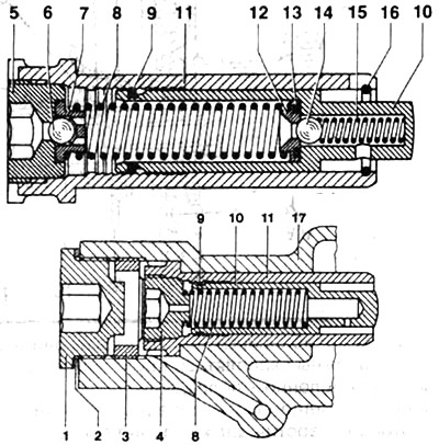
Installing the chain tensioner (6 cylinder engine): 1. Bolt-plug. 2. O-ring. 3. Threaded ring. 4. Oil jet. 5. Ball landing ring. 6. Ball. 7. Ball casing. 8. Pressure spring. 9. Groove spring. 10. Pressure piston. 11. Body. 12. Valve washer. 13. Ring. 14. Ball. 15. Pressure spring. 16. Support ring. 17. Cylinder head.
Chain tensioners of various designs, A or B, can be installed.
Turn the engine over and check the timing marks.
If necessary, check the valve timing.
Since the push rod of the chain tensioner on 6-cylinder engines cannot be pushed back, the chain tensioner must be dismantled after each removal and the push rod is set to position A.
During assembly work on the chain drive, e.g. when removing the camshaft gears or damper, the pressure spring must first be removed with the chain tensioner installed.
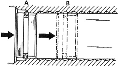
A - chain tensioner in the installation position
B - chain tensioner in working position
Install hydraulic valve clearance compensators and rocker arms.
Insert the ignition distributor drive shaft and install the ignition distributor.
Once again, set the engine to the TDC position of the first cylinder and check the adjustment marks on the balancing disk, camshafts and ignition distributor.
Adjust valve clearance.
If necessary, check the position of the hydraulic valve clearance compensator and correct it (V8 engines). On 6-cylinder engines, valve clearance is measured with a flat feeler gauge between the sliding surface and the main surface of the camshaft cam.
On the installed assembled engine, you must first remove the tension springs, as well as the rubber gaskets for the spark plug holes. A flat feeler gauge should be tight when properly adjusted.
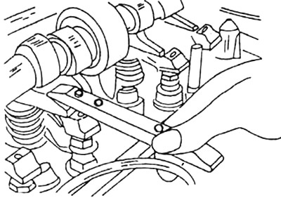
To adjust the valve clearance, the corresponding camshaft cam must be set so that the cam nose does not press on the rocker, but stands opposite and vertical to the sliding plane.
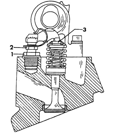
Engine valve control mechanism: 1. Threaded sleeve. 2. Valve adjusting bolt. 3. Pressure device (pusher)
Valve clearance can be checked or adjusted on a cold or warm engine. If the adjustability is insufficient, replace the pressure device. If the torque of the valve adjusting screw is less than 20 Nm, the adjusting screw or the adjusting screw together with the threaded bush must be replaced. 4 Install and tighten the valve cover.
Install intake and exhaust manifolds, mixture regulator and air line, carburetor, fuel pump, water pump and fan.
Install the oil filter and dipstick tube.
Screw in the spark plugs.
Install alternator and belt.
Screw in the engine mounts.
Install the driven disc with a suitable centering rod on the inside of the flywheel.
Install the clutch and tighten the clutch bolts evenly (criss-cross) necessary moment.
For vehicles with automatic transmission, install the transfer disc.
Install remaining engine parts. Attach gearbox to engine.
The engine is ready for installation.
Pour oil into the engine.