



Sequence of works


1. Remove the protective sleeve, rubber supports and spacer sleeve from the rod.
2. Check the piston rod for scratches and bends. A bent piston rod should stick when compressed.
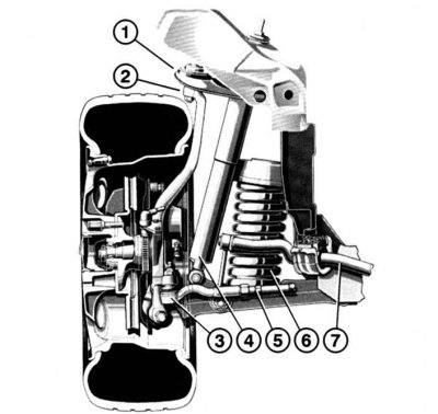
Fig. 7.11. Front wheel suspension in section: 1 – upper transverse arm; 2 – steering knuckle with upper ball joint; 3 – steering rod end with ball joint; 4 – shock absorber; 5 – steering rod; 6 – coil spring; 7 – anti-roll bar
3. The gas and oil chambers in shock absorber 4 (Fig. 7.11) are separated by a separating piston. Check the oil volume as follows: push the rod to the level of the separating piston and measure the rod travel. New shock absorbers have a play of 0–2 mm, the rod travel value for replacement is 20 mm.
Material based on data from the portal MERCEDESMAN
4. Push the rod in to the level set on the vehicle and release. There should be no popping or hissing sounds.
5. Shock absorbers can be replaced one at a time, but it is important to observe the color marking. For old shock absorbers, paired replacement is recommended.