
Removing the cylinder head
If the engine has not yet been removed from the vehicle, first carry out the following operations:
1. Disconnect the wire «masses» from the battery.
2. Remove the intake and exhaust manifolds.
3. Remove the compressor of an air conditioning system where it is available.
4. Remove the ignition distributor, high voltage wires and spark plugs.
5. Remove the rear suspension automatic level control hydraulic pump, where present.
6. Disconnect all wires and hoses and drain the liquid from the cooling system.
7. Remove the oil dipstick tube, where present.
M123 engine
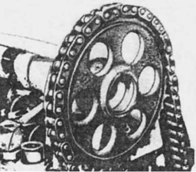
Removing the camshaft gear
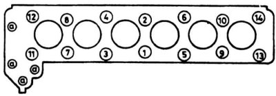
The sequence of tightening the cylinder head bolts on the M 123 engine
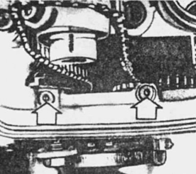
The arrows indicate the small cylinder head bolts in the timing chain opening (M 123 engine)
1. Turn away nuts and remove a valvate cover.
2. Loosen the clamps and remove the bypass hose between the water pump and the thermostat housing. Remove the thermostat housing.
3. On cars with an automatic transmission remove a rack between the right suspension bracket of the engine and a head of cylinders.
4. Turn the crankshaft pulley bolt until both valves in the 1st cylinder are closed and the TDC mark on the vibration damper is aligned with the arrow to set the ignition timing.
5. Mark the relative positions of the chain and camshaft sprocket.
6. Turn away a stopper of a chain tensioner and remove a spring. Then unscrew the nuts and remove the tensioner body together with the plunger.
7. Turn away a bolt of an asterisk of a camshaft, having blocked asterisks by means of the metal core passed in one of openings.
8. Move the sprocket, remove it from the chain and tie it to one side. Keep in mind that the marks on the sprocket are on the outer face of the sprocket.
9. Turn away bolts and remove the ventilating tube going from the water pump to a head of cylinders.
10. Turn away bolts of a head of cylinders in sequence, reverse to that shown in drawing, by means of an internal hex socket wrench. Don't forget the two bolts in the camshaft tunnel. Keep in mind that the longer bolts are on the camshaft bearings.
11. Ask an assistant to lift the chain and keep its guide inside, and remove the cylinder head from the block yourself. If it does not give in, tap on it with a wooden mallet. Do not insert the lever into the gasket slot to avoid damaging the mating surfaces. Place the cylinder head on wooden stands to avoid damaging the valves.
12. Remove the cylinder head gasket from the block.
M110 engine

Removing the valve lifter (engine M 110)
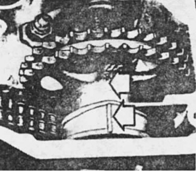
TDC marks on the camshaft gear and its housing (engine M 110)
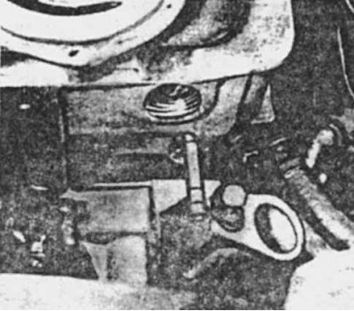
Removing the side rail studs (engine M 110)
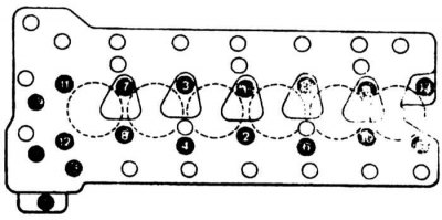
The sequence of tightening the cylinder head bolts on the M 110 engine
1. Remove the vacuum pump (where it is designed).
2. Using hex socket wrenches, remove the bolts and remove the front camshaft covers.
3. Turn away bolts of a tube of return of oil.
4. Loosen the clamps and remove the bypass hose from the water pump to the thermostat housing. Remove the case.
5. Turn away nuts and remove a valvate cover.
6. Separate the springs from the cam followers with a screwdriver.
7. Rotate the crankshaft pulley bolt until the tops of the lobes of the cams in the 1st cylinder are in the upper position, then lower the valves of the levers so that the cam followers are removed. Mark the positions of the followers. Repeat this operation for the rest of the valves.
8. Rotate the crankshaft pulley bolt until the tops of the cam protrusions in the 1st cylinder are in the upper position and the TDC mark on the vibration damper is aligned with the valve timing indicator. Make sure that the marks on the camshaft sprocket are aligned with the marks on its housing.
9. Turn away bolts of sprockets of a camshaft, having blocked sprockets by means of the metal bar passed in one of openings.
10. Remove the radiator. This operation is desirable as it will free up space for work.
11. Using a hex socket wrench, unscrew the chain tensioner plug and loosen the internal plug about two turns. Loosen the outer race and remove the tensioner. If it sticks, unscrew the internal plug and screw in the bolt to remove the assembly.
12. Knock out the pins with a hammer and remove the upper guide rod from the camshaft housing.
13. Move the camshafts all the way back, remove the spacers and chain from the sprockets, and tie the chain to one side.
14. Turn away a stopper of a cover, take out a basic pin and remove a directing sprocket of a chain.
15. Knock out the pins with a hammer and remove the side guide rod from the cylinder head.
16. Turn away bolts of fastening of a head of cylinders in sequence, return to that shown in drawing, by means of a hex internal socket wrench. Don't forget the two bolts in the chain opening.
17. Have an assistant lift the chain and hold the right chain guide inside, then remove the cylinder head from the block. If it sticks, release it by tapping with a wooden mallet. Do not insert the levers into the gasket slot to avoid damaging the mating surfaces. Place the cylinder head on wooden stands to avoid damaging the valves.
18. Remove the cylinder head gasket from the block.