
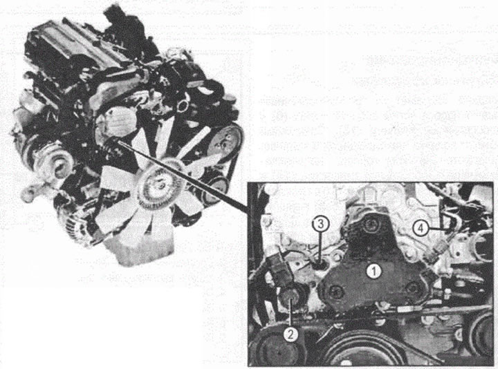
VN 2.120
1. injection pump (M41)
2. Fuel quantity control valve (Y94)
3. Fuel temperature sensor (B50)
4. High pressure fuel line
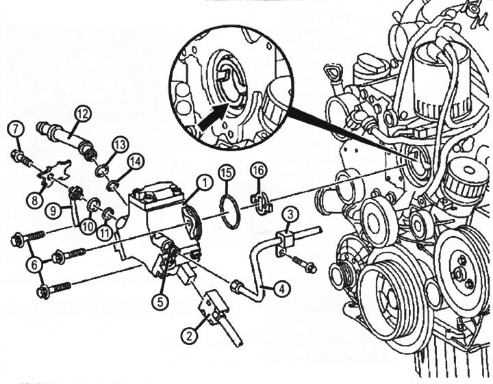
VN 2.121
injection pump. Placement and construction
1. injection pump
2. Electrical connector
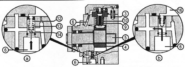
VN 2.122
injection pump. Operating principle
A. Throttle valve closed:
3. High pressure channels
4. Eccentric cam
5. Eccentric shaft
6. Input channel
9. Plungers
10. Plunger springs
12. Throttle valve spring
b. Throttle valve open:
13. Throttle valve piston
14. Throttle valve metering port
16. Return flow
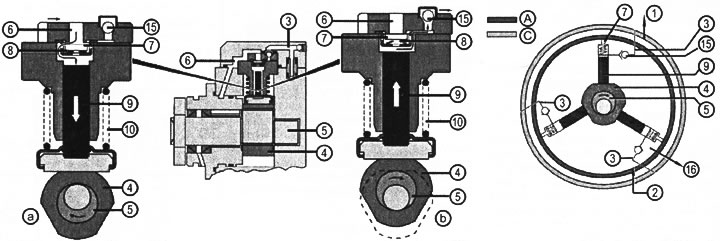
VN 2.123
injection pump. Operating principle
A. Incoming stream
b. High pressure channel
C. Pressure from priming pump
D. High pressure
1. High pressure fuel line
2. Inlet fuel line
3. High pressure channels
4. Eccentric cam
5. Eccentric shaft
6. Input shaft
7. Valve disc
8. Valve spring
9. Plungers
10. Plunger return springs
15. Ball valve
16. Return flow
Purpose
Creation and maintenance of high pressure in the fuel manifold, the required fuel pressure (from 20 to 135 MPa (from 200 to 1350 bar).
Accommodation
The injection pump is located on the front cover of the cylinder head.
Design
High pressure fuel pump is a three-plunger cam-type pump with a radial arrangement of plunger pairs in a star pattern. The injection pump is driven at a speed approximately 1.3 times higher than the camshaft speed.
Functioning
Low pressure circuit
Fuel is supplied from the fuel priming pump through the inlet port (6) to throttle valve (13). Possible air residues in the fuel are carried away by the fuel flow directed through the throttle opening (14) into the return flow cavity (16). At pressures over 0.04 MPa (0.4 bar) valve piston (13) is displaced, opening access to fuel in the annular channel for supplying fuel to the plungers (9),
Eccentric shaft (5) with eccentric cam (4) pushes plungers (9) three pumping elements. Plungers are returned using springs (10). Fuel leaks through the plunger pairs are collected in the return cavity.
High pressure circuit
A. Cylinder filling
Plunger (9) under the action of a return spring (10) moves towards the eccentric shaft. Fuel from the fuel priming pump is supplied through the low pressure annular channel (6), valve disc (7) and valve spring (3) into the pressure cylinder. ball valve (15) prevents backflow of fuel from the high pressure channel (3) into the low pressure cavity.
b. Building high pressure
Plunger (9), pushed by an eccentric cam (5), displaces fuel into the high pressure channel (3) through ball valve (15). In this case, the pumped volume of fuel is cut off from the low pressure cavity (6) with valve disc (6).