
Air supply system (functional diagram, the placement of elements is shown conditionally)
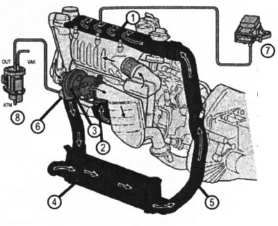
VN 2.108
1. Intake manifold
2. Exhaust manifold
3. Turbocharger
4. Air cooler
5. Compressed air duct
6. Vacuum boost control device
7. Intake manifold pressure sensor (B28)
8. Vacuum converter that controls the ATM boost pressure control damper. Atmospheric pressure output OUT. Control vacuum output VAK. Vacuum supply from a vacuum pump (Y31/5)
Turbocharger with fixed gas turbine geometry
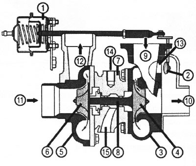
VN 2.109
1. Vacuum boost pressure control device
2. Bypass damper
3. Blower housing
4. Compressor wheel
5. Gas turbine housing
6. Turbine wheel
7. Turbine bearing housing
8. Turbine aal
9. Supercharger inlet (outside air)
10. Supercharger outlet (compressed air)
11. Filed exhaust gases to the turbine wheel
12. Exhaust gas output
13. Bypass hole
14. Oil supply
15. Oil return to crankcase
Turbocharger with variable geometry gas turbine guide vanes
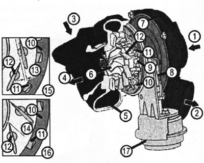
VN 2.110
1. Compressor inlet (outside air)
2. Compressor outlet (forced air)
3. Supply of exhaust gases to the turbine wheel
4. Exhaust gas outlet
5. Turbine body
6. Turbine wheel
7. Compressor body (supercharger)
8. Rod control
9. Timing ring drive arm
10. Synchronization (regulating) ring
11. Rotary arm of guide vane
12. Guide vane
13. Air gap in the position of the blades «closed»
14. Air gap in the position of the blades «open»
15. Guide vanes «closed»
16, guide vanes «open»
17. Vacuum boost pressure control chamber
Purpose
The boost pressure supply system is designed to bring the amount of air supplied to the cylinders in line with the power required at the moment and with external conditions.
The charge pressure is controlled by means of a damper from an engine speed of approximately 2000 rpm, depending on the engine load and engine speed, by opening it in the bypass line of the turbocharger. The control flap is closed until the speed reaches 2000 rpm (boost pressure still not enough).
Functioning
Exhaust gases are directed through the exhaust manifold into the turbine housing to the turbine wheel. The energy of the exhaust gas flow drives the turbine wheel into rotation. On the same shaft with the turbine wheel is the supercharger turbine wheel, which, rotating, creates a stream of air directed under pressure into the engine cylinders. Maximum turbine speed (in high altitude conditions) can reach 18000 rpm.
The boost pressure is controlled in various ways.
According to the first method, with the help of a controlled damper, the throughput of the bypass opening is regulated, which directs the exhaust gases around the turbine, thus reducing its productivity.
According to the second method, the direction and intensity of the gas flow is regulated directly in front of the turbine wheel blades. On fig. VN 2.110 shows how when the angle of installation of the guide vanes changes, the clearance section of the gap between the blades and the angle at which the gas flow is directed to each blade of the turbine wheel change.
The advantages of a turbocharger with a variable turbine guide vane geometry are:
- increase in boost pressure, especially in the region of low engine speeds;
- increased torque as a result of improved cylinder filling;
- reduction of harmful emissions in the composition of exhaust gases as a result of an increase in the amount of air supplied to the cylinders;
- increased engine power as a result of higher boost pressure combined with reduced exhaust gas back pressure