
Purpose
The nozzles are designed to inject atomized fuel into the combustion chamber with the most advantageous shape «torches» spraying.
Design
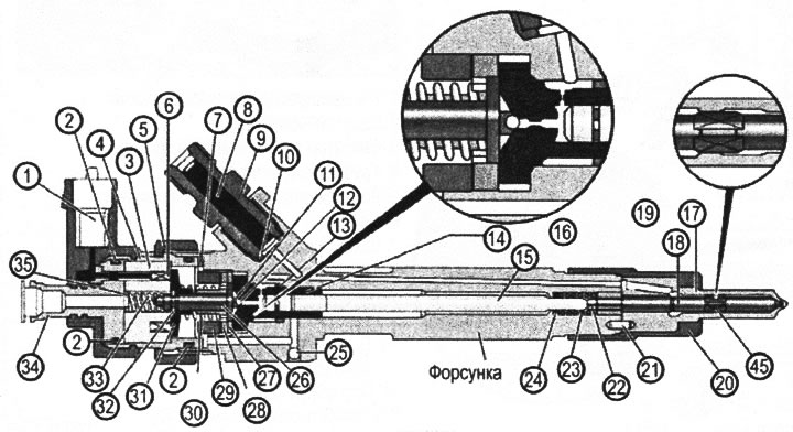
VN 2.128
1. Electrical connector
2. O-ring
3. Solenoid coil
4. Sleeve
5. Union nut for fastening the solenoid
6. Solenoid
7. Adjustable shim
8. Filter
9. High pressure pipe fitting
10. Sealing gasket
11. Ball guide
12. Valve ball
13. O-ring
14. Valve guide
15. Valve piston
16. Valve assembly
17. Atomizer body
18. Atomizer needle
19. Atomizer
20. Union nut for fastening the atomizer
21. Pin
22. Pusher
23. Atomizer spring
24. Gasket
25. Ball used as a plug
26. Solenoid core
27. Adjustable shim
28. Solenoid Armature Disc
29. Valve pressure screw
30. Solenoid spring
31. Plate
32. Locking washer
33. Spring
34. Connection
35. Gasket
45. Needle guide
Accommodation
The injectors are located in the cylinder head and are connected to the high pressure fuel manifold using high pressure pipes.
Note: atomizer spring (23) holds the needle (18) in the locking position of the sprayer at a pressure difference in the upper and lower chambers of not more than 40 bar (4 MPa).
2. Solenoid not energized, high pressure present, no injection.
In this phase of operation of the injector, pressure from the HPTC is supplied through the supply channel to the lower chamber, as well as through the throttle opening to the upper chamber. The fuel pressure in the upper and lower chambers is balanced. The atomizer needle return spring holds the needle in the closed position of the atomizer valve. There is no injection.
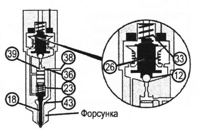
3. Start injection (the solenoid valve is open, the nozzle is energized).
When voltage is applied to the solenoid valve coil (6) solenoid core (26) retracts by compressing the spring (33). This opens the ball valve (12) and fuel from the upper chamber (39) through the orifice (37) the pressure relief channel flows into the fuel return circuit. pressure at the top (balancing) camera is reduced. Unbalanced fuel pressure in the lower chamber creates a force that lifts the needle.
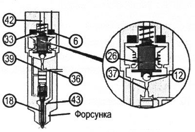
4. Injection (the solenoid valve is open, the nozzle is energized).
While holding the ball valve (12) open unbalanced chamber pressure (43) holds the atomizer needle (18) in the open state. The pressure difference at the top (39) and bottom (43) chambers is provided by the ratio of the throughput values of the throttle holes (36) And (37).
5. End of injection (solenoid valve closed).
When power is removed from the solenoid coil, the valve closes. In this case, the pressure in the upper chamber is restored to a value equal to the pressure in the lower chamber. Return spring force (23) closes the spray valve.
Functioning
1. Solenoid not energized, no injection.
Pressure in the supply channel in (38) high pressure is approximately equal to atmospheric pressure. ball valve (12) locked by spring force (33), acting on the core of the solenoid (26).
VN 2.129
Solenoid not energized, no injection
6. Solenoid
12. Valve ball
18. Atomizer needle
23. Atomizer spring
26. Solenoid core
33. Spring
VN 2.129
Start of injection (the solenoid valve is open, the nozzle is energized)
36. Calibrated hole (throttle function)
37. Pressure relief channel from the upper chamber
38. High pressure channel

VN 2.129
End of injection (solenoid valve closed)
39. Upper valve chamber (balancing pressure)
42. Fuel return flow
43. Lower valve chamber (needle lifting pressure)
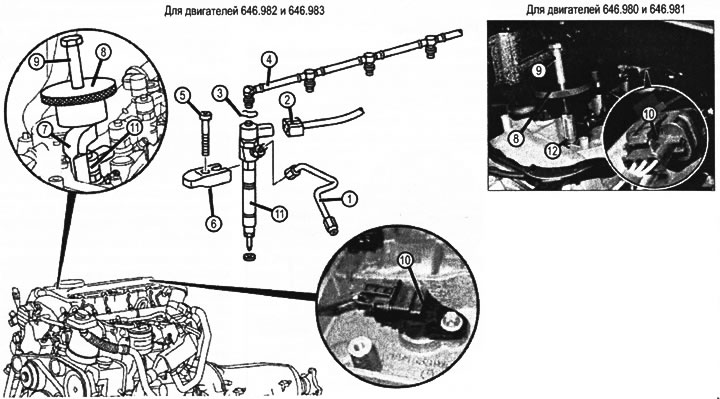
VN 2.130
1. High pressure fuel line
2. Electrical connector
3. Fuel return pipe retainer
4. Fuel return pipe
5. Injector clamp screw
6. Clamp
7. Grab the impact puller
8. Impact puller weight
9. Guide rod (screw) impact puller
10. Camshaft position sensor (B6/1, B6/17)
11. Nozzle (Y76)
12. Thread adapter
Removal and installation
1. Remove clamp (6).
2. Remove nozzles (11), If the nozzles cannot be removed, install the gripper (7) to the place of pressing (6) and with an impact puller (8) And (9) remove injectors (11) along with the sealing ring.
3. Clean the nozzles and nozzle openings with brass brushes of suitable sizes, lubricate the nozzles with special grease, blow out the openings and protect them from contamination by first inserting plugs.
Attention: removal of injectors on engines 646.980 and 646.981 differs from that described above (for engines 646.982 and 646.983) because instead of capturing (7) thread adapter is used (12).
4. Install in reverse order. When installing nozzles, to prevent the appearance of excessive stresses in the high pressure pipelines, they should be installed (pipelines) on the injectors until the final tightening of the fastening of the injectors,
5. Check the fuel system for leaks with a short engine start.
Tightening torques for threaded connections
Injector clamp screw 7 Nm + 90°.