
Removing
1. Remove the cylinder head and oil pump.
2. Unscrew the bolts of the connecting rod caps 1 (see fig.5.29). Mark connecting rod bearings and caps 1 of each cylinder. Do not mix top liners.
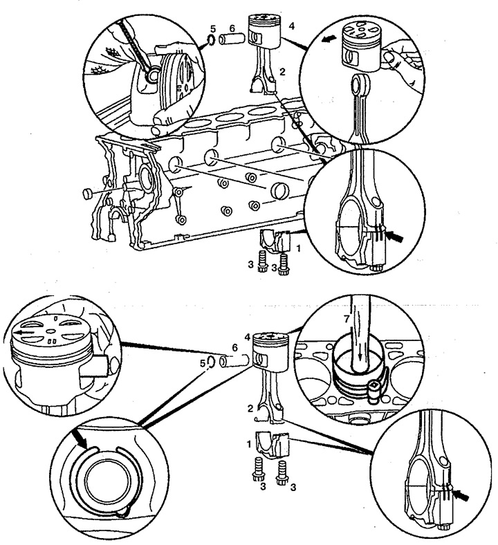
Pic. 5.29. Pistons:
1. Connecting rod cap,
2. Connecting rod,
3. Bolt,
4. Piston,
5. Retaining ring,
6. Piston pin.
3. Remove the connecting rods 2 upwards together with the pistons 4. If the direction arrow on the piston cannot be recognized, apply it again.
4. Remove the retaining ring 5 of the piston pin 6. Do not damage the piston 4.
5. Press piston pin 6 out.
6. Check up rods 2 on absence of distortion of openings and grooves.
Installation
7. Lubricate the piston and connecting rod.
8. Install the piston 4 on the connecting rod 2 in the direction of the travel direction arrow (in the opposite direction of power flow).
9. Insert the retaining ring 5 of the piston pin 6 into the groove in the piston 4.
10. Install the tension band 7 for the piston rings and tighten it. Piston ring lock: 120°.
11. Install piston 4.
12. Check and, if necessary, replace the bolts 3 fastening the connecting rod caps.
13. Insert the liners into the cap 1 of the connecting rod and into the connecting rod 2. The liners with the oil channel must be installed in the connecting rod 2, otherwise the liners will not be lubricated. The anti-twisting bushing retainers must be installed in the grooves of the connecting rods 2 and the connecting rod caps 1.
14. Tighten the connecting rod cap bolts 1. The connecting rod cap 1 and connecting rod 2 are marked (arrows).
15. Rotating a cranked shaft, check backlashes.
16. Install the oil pump.
17. Measure piston protrusion. It should be 0.38-0.62 mm. Install a cylinder head gasket of normal or replacement thickness.
18. Install the cylinder head.