
2. Block the intake camshaft. Insert pin 3 through the hole in the first camshaft bearing cap into hole A in the intake camshaft pulley 2.
3. The two marks B on the pulleys of camshafts 1 and 2 must be located one opposite the other and the marks on the camshaft and the camshaft bearing cap must be aligned (arrows) (see fig.5.24).
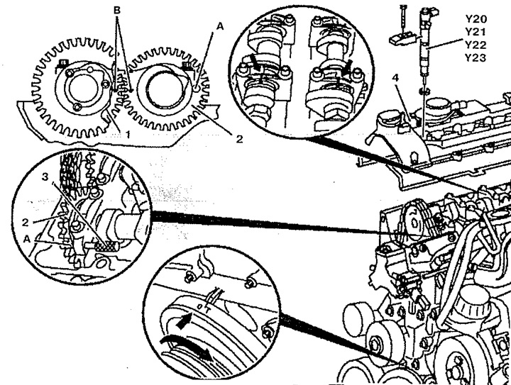
Pic. 5.24. Checking the basic position of the camshafts:
1. Exhaust camshaft pulley,
2. Intake camshaft pulley,
3. Locking pin,
4. Cylinder head cover,
A. Hole in the intake camshaft pulley,
B. Tags,
Y20. Nozzle 1,
Y21. Nozzle 2,
Y22. Nozzle 3,
Y23. Nozzle 4.