
Removing
1. Disconnect the negative cable from the battery.
2. Drain the coolant.
3. Remove Y20 injectors (see fig. 5.25).
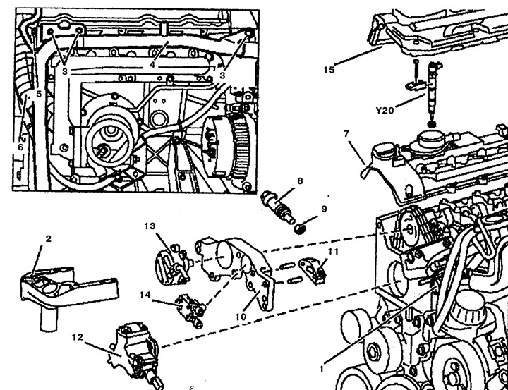
Pic. 5.25. Cylinder head:
1. Thermostat housing,
2. Top engine mount bracket,
3. Bolt,
4. Pipe of the cooling system,
5. Nut,
6. Air inlet pipe,
7. Cylinder head cover,
8. Chain tensioner,
9. O-ring,
10. Front cylinder head cover,
11. Upper sliding arm,
12. High pressure fuel pump,
13. Vacuum pump,
14. Fuel pump,
15. Cover.
4. Disconnect the pipes of the cooling system from the thermostat housing 1.
5. Disconnect the fuel lines and remove the fuel filter 16.
6. Remove the fuel filter mounting bracket 17 to the cylinder head 27 (see fig.5.26).
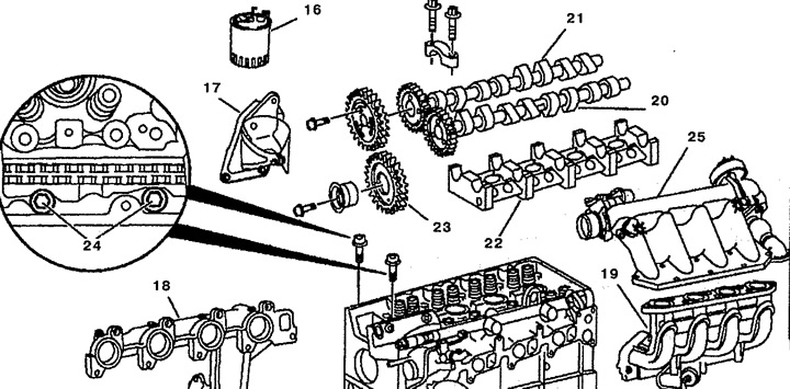
Pic. 5.26. Cylinder head:
16. Fuel filter,
17. Fuel filter mounting bracket,
18. Exhaust manifold,
19. Intake manifold,
20. Intake camshaft,
21. Exhaust camshaft,
22. Camshaft housing,
23. Intermediate gear for high pressure fuel pump,
24. Bolt,
25. Mixing chamber with EGR valve.
7. Disconnect the wiring connectors from the coolant temperature sensor, the fuel pressure sensor in the distributor and the fuel pressure control valve.
8. Remove the exhaust manifold 18.
9. Remove the top right engine bracket 2.
10. Unscrew the bolt 3 fastening the pipe of the cooling system 4 to the cylinder head 27.
11. Remove intake manifold 19.
12. Unscrew the nut 5 fastening the compressed air supply pipe 6 to the cylinder head 27.
13. Remove the cylinder head cover 7.
14. Set the piston of the first cylinder to TDC. The marks on the camshaft and camshaft bearing cap must be aligned.
15. Block the flywheel with a retainer.
16. Remove the timing chain tensioner 8.
17. Remove the front cylinder head cover 10.
18. Remove the upper sliding arm 11.
19. Remove camshafts 20 and 21 and camshaft housing 22.
20. Remove the high pressure fuel pump 12.
21. Remove the intermediate gear 23 of the high pressure fuel pump drive 12.
22. Unscrew the bolts 24 securing the timing chain cover to the cylinder head 27.
23. Loosen the cylinder head mounting bolts 26 in the sequence shown in fig. 5.27 and unscrew them.
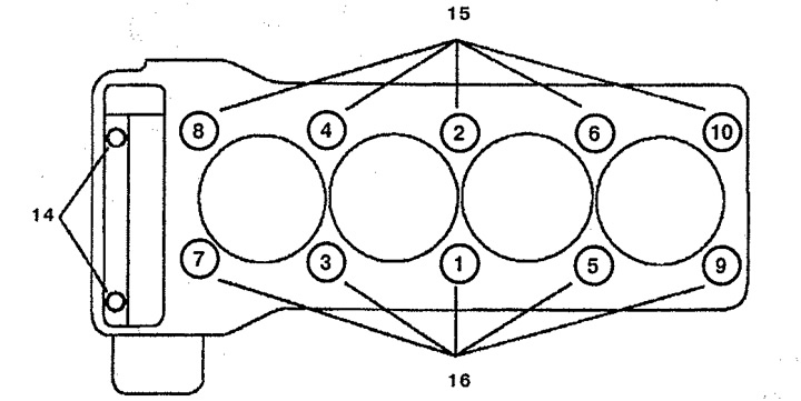
Pic. 5.27. The sequence of loosening and tightening the cylinder head bolts.
14. Bolts М8х90,
15. Bolts M12x102.
24. Remove the cylinder head 27. To do this, attach the lift to the lugs attached to the cylinder head (see fig.5.28).
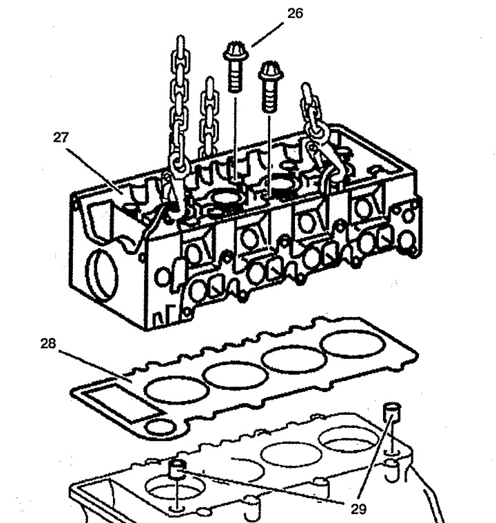
Pic. 5.28. Cylinder head:
26. Bolt of fastening of a head of the block of cylinders,
27. Cylinder head,
28. Gasket,
29. Guide pins.
25. Wipe the sealing surfaces and threaded holes.
Installation
26. Installation is made in an order, the return to removal. Replace cylinder head gasket
28. Make sure that the guide pins 29 for installing the cylinder head are correctly installed.
27. Lubricate the threaded holes and contact surfaces of the heads of the cylinder head bolts 26 and insert them. Tighten bolts of fastening of a head of the block of cylinders in the order specified in fig. 5.27. Tighten bolts 15 to stage 1, bolts 14 fully, then bolts 15 to stage 2, check bolts 14 and, if necessary, tighten them. Tighten bolts 15 to stage 3.