
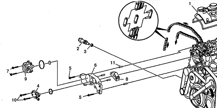
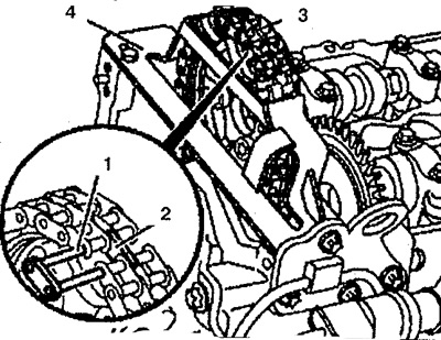
Pic. 5.16. Timing chain replacement:
1. Cylinder head cover,
2. Timing chain tensioner,
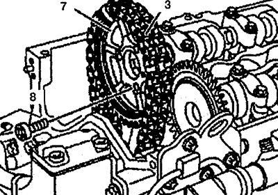
3. Seal,
4. Fuel pump,
5, 7, 10. Bolts,
6. Front cover,
8. Upper guide arm,
9. Vacuum pump,
11. Guide pin.
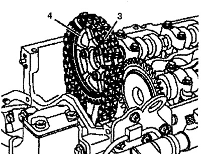
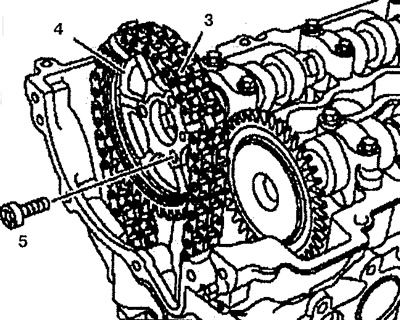
2. Disconnect the timing chain. Fasten the timing chain 3 to the camshaft pulley 4 with a tie band (see fig.5.17a).
Pic. 5.17a. Attach the timing chain 3 to the camshaft pulley 4 with a tie strap.
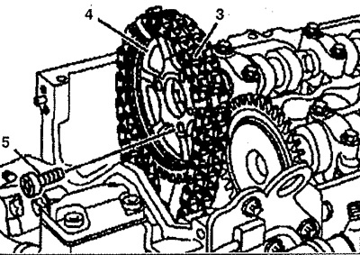
3. Remove the camshaft pulley 4 together with the attached timing chain 3 (see fig. 5.17 b).
Pic. 5.17 b. Remove the camshaft pulley 4 together with the attached timing chain 3.
4. Screw in stop spindle 02 (602 589 04 63 00) together with stop pin 02a (602 589 04 63 01) to separator 03 (602 589 02 33 00) (see fig.5.17c).
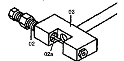
Pic. 5.17c. Screw the stop spindle 02 together with the stop pin 02a into the cage 03.
5. When installing the stop spindle, make sure the stop pin is located on the left side of the chain link pin (arrow) (see page 5.17d).
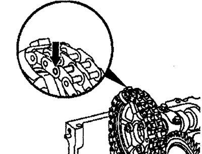
Pic. 5.17. Make sure the stop pin is located on the left side of the chain link pin (arrow).
6. Install the timing chain separator 1 of the removed camshaft pulley (see fig.5.17e). The timing chain pin can only be removed if the camshaft pulley is removed.
Pic. 5.17d. Install the timing chain separator 1 of the removed camshaft pulley.
7. Screw in the thrust spindle 2 and disconnect the timing chain.
8. Unscrew stop spindle 2 and remove cage 1.
9. Install the camshaft pulley 4 with chain 3 (see fig.5.17e). Do not disconnect the chain from the pulley.
Pic. 5.17e. Install camshaft pulley 4 with chain 3.
10. Remove the pressed pin 1 from separator 03 (see fig. 5.17g).
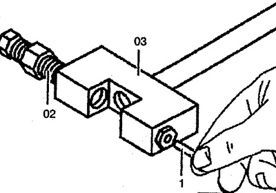
Pic. 5.17g. Remove pressed pin 1 from separator 03.
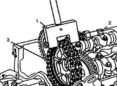
11. Install retainer 1 on the cylinder head (see fig.5.18a).
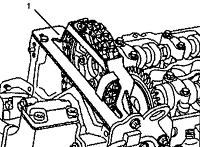
Pic. 5.18a. Establish a clamp 1 on a head of the block of cylinders.
12. Remove the timing chain tie strap.
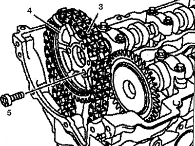
13. Connect the new chain 3 to the old chain 2 with link 4.1, plate 4.2 and blocking element 4.3 and secure them (see fig. 5.18 b).
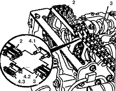
Pic. 5.18 b. Attach new chain 3 to old chain 2 with link 4.1, plate 4.2 and blocking element 4.3 and secure them.
14. Install the new chain 3 and rotate the crankshaft slowly in the direction of rotation until both ends of the new chain 3 are visible (see fig.5.18c).
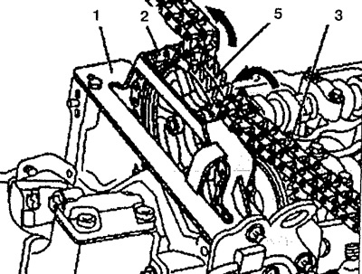
Pic. 5.18c. Install a new chain 3 and rotate the crankshaft slowly in the direction of rotation until both ends of the new chain 3 are visible.
15. Remove blocking element 4.3, outer plate 4.2, link 4.1 and disconnect the old chain from the new one (see fig.5.18d).
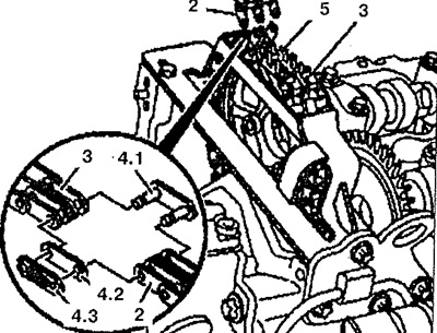
Pic. 5.18g. Remove blocking element 4.3, outer plate 4.2, link 4.1 and disconnect the old chain from the new one.
16. Fix a new chain 3 on a camshaft pulley 5.
17. Insert the new link 1 and the new middle plate 2 into the end of the chain 3 (see fig.5.19a).
Pic. 5.19a. Attach the new chain 3 to the camshaft pulley 5. Insert the new link 1 and the new middle plate 2 into the end of the chain 3.
18. Remove retainer 4 from the cylinder head.
19. Remove the camshaft pulley 4 with the chain 3 installed on it (see fig. 5.19 b).
Pic. 5.19 b. Remove the camshaft pulley 4 with the chain 3 installed on it.
20. Install the insert in the riveting tool 5 and fasten it (see fig. 5.19v).
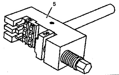
Pic. 5.19c. Insert the insert into the riveting tool 5 and fasten it.
21. Press the new link 1 into the riveting tool 5 until it stops (see fig.5.19d).
Pic. 5.19 Press the new link 1 into the riveting tool 5 until it stops.
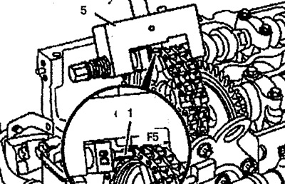
22. Unscrew the stop spindle and remove the riveting tool 5. Remove inserts D9 and F5 from the riveting tool.
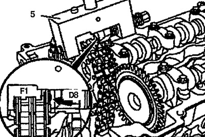
23. Install insert F1 in rivet tool 2 and secure it with bolt 3 (see fig.5.19e).
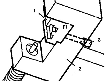
Pic. 5.19d. Insert insert F1 into riveting tool 2 and fasten it with bolt 3.
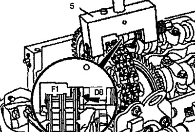
24. Install insert D8 in riveting tool 5 (see fig.5.19e).
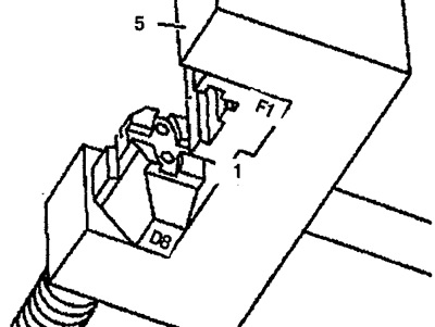
Pic. 5.19e. Install insert D8 in riveting tool 5.
25. Insert the new outer plate 6 into the sliding insert D8 (see fig.5.19g).
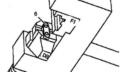
Pic. 5.19g. Insert the new outer plate 6 into the sliding insert D8.
26. Install the riveting tool 5 so that the guide abuts (arrow) (see fig.5.19h).
Pic. 5.19z. Install the riveting tool 5 hook so that the guide rests (arrow).
27. Screw in the riveting tool spindle as far as it will go.
28. Remove rivet tool 5.
29. Rotate the D8 insert against the rivet profile (arrow) (see fig.5.19k).
Pic. 5.19k. Rotate the D8 insert against the rivet profile (arrow).
30. Install the riveting tool 5 in the middle of the pin (arrow) (see fig.5.19l).
Pic. 5.19l. Install riveting tool 5 in the middle of the pin (arrow).
31. Tighten the riveting tool spindle 5 until it stops.
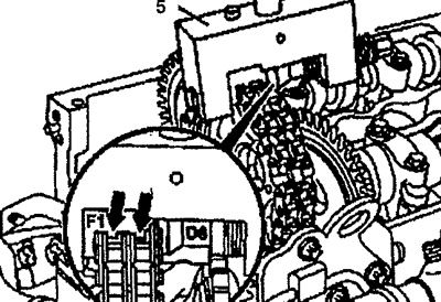
32. Check the rivet (arrows), if necessary, repeat the riveting process (see fig. 5.19m).
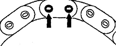
Pic. 5.19m. Check Rivet (arrows), repeat the riveting process if necessary.
33. Install the camshaft pulley 7 on the shaft with the chain 3 installed on it (see fig.5.19h).
Pic. 5.19n. Install the camshaft pulley 7 on the shaft with the chain 3 installed on it.
34. Remove the straps.
35. Install the timing chain slide lever.