



Contents: Removal ↡ Installation ↡
Removal
1. Remove injectors Y 20, Y 21, Y 22, Y 23 (see figure 5.6).
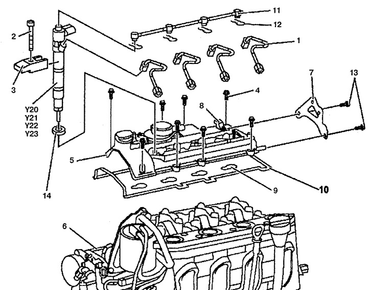
Figure 5.6. Cylinder head cover:
1. Fuel injection line,
2, 4, 13. Bolts,
3. Tension lever,
5. Cylinder head cover,
6. Cylinder head,
7. Bracket,
8. Crankshaft speed sensor,
9, 10. Gasket,
11. Fuel drain line,
12. Retainer,
14. Nozzle seal,
Y20. Nozzle 1,
Y21. Nozzle 2,
Y22. Nozzle 3,
Y23. Nozzle 4.
2. Remove bracket 7 for fastening the exhaust gas recirculation valve from cylinder head cover 5.
3. Disconnect the wiring connector from the camshaft speed sensor 8.
4. Disconnect the pipes running above the cylinder head cover 5 and secure them to the side.
5. Unscrew bolts 4 securing cylinder head cover 5 and remove it.
6. Remove the camshaft speed sensor 8.
Installation
7. Installation is carried out in the reverse order of removal. Wipe the sealing surfaces. Replace gaskets 9 and 10 of cylinder head cover 5. Do not fully tighten bolts 4 securing injectors Y20-Y23 until they are correctly installed directly in cover 5. Otherwise, this may result in fuel leakage and excessive stress on the injectors in cylinder head 6, as well as excessive loads on fuel lines 1.