
Removal and installation of the engine with a subframe
Removing
1. Place the vehicle in the service position (only on vehicles with rear air suspension).
2. Disconnect the negative cable from the battery.
3. Drain the coolant from the cooling system and empty the air conditioning system.
4. Remove the front bumper, front cross member, grille, air filter, right headlight, air intakes, front wheels and washer reservoir.
5. Disconnect pipe 4 of the cooling system from the cycle valve Y37 (see fig.5.1).
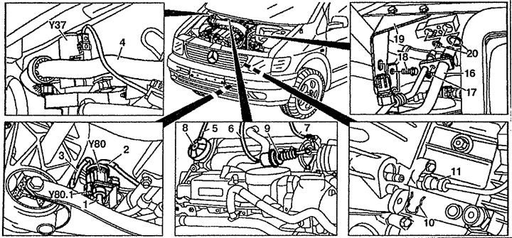
Pic. 5.1. Removal and installation of the engine with a subframe:
1, 2, 3, 5, 6, 7. Vacuum tubes,
4. Cooling system tube,
8.EGR valve,
9. Throttle valve,
10. Retainer,
11. Hydraulic pipeline,
16. Tube of the air conditioning system,
17. Nut,
18. Bolt,
19. Bracket,
20. O-ring,
Y37. cycle valve,
Y80. Vacuum Compressed Air Pressure Sensor,
Y80.1. Connector wiring vacuum compressed air pressure sensor.
6. Disconnect fuel lines 21 and 22 (see fig.5.2).
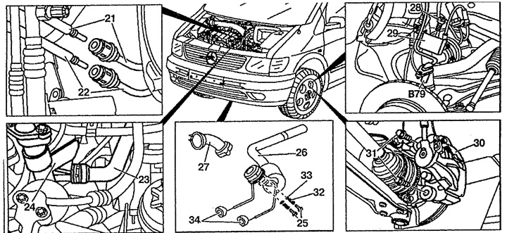
Pic. 5.2. Removal and installation of the engine with a subframe:
21. Fuel injection line,
22. Drain fuel line,
23. Pipe of the cooling system,
24. EGR cooling unit,
25, 28, 31. Bolt,
26. Exhaust system,
27. Exhaust pressure chamber,
29. Heat shield,
30. Brake caliper,
32. Spring,
33. Gasket,
34. Rubber feet,
B79. ABS wheel speed sensor.
7. Disconnect the branch pipe 23 from the cooling block of the EGR 24 system.
8. Disconnect vacuum tubes 5, 6 and 7.
9. Disconnect the shift lever.
10. Disconnect wiring from engine.
11. Disconnect the retainer 10 of the hydraulic line 11 from the clutch slave cylinder and remove it.
12. Disconnect the drain tube from the washer reservoir.
13. Unscrew the bolt 18 from the bracket 19.
14. Disconnect tubes 16 of the air conditioning system from the expansion valve. Replace O-ring 20.
15. Turn off a bolt 25 fastenings of the chamber with the increased pressure of the fulfilled gases.
16. Remove exhaust system 26 as an assembly.
17. Remove the Y80 turbo boost pressure control vacuum sensor from the bracket on the subframe 35 (see fig.5.3).
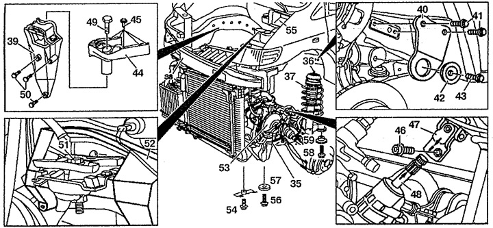
Pic. 5.3. Removal and installation of the engine with a subframe:
35. Subframe,
36. Nut,
37. Shock absorber,
38. Front cross beam,
39. Right engine mount,
40. Stove,
41, 43, 45, 46, 49, 50, 51, 56, 58. Bolts,
42. Rubber support,
44. Upper engine mount,
47. Steering shaft hinge,
48. Steering gear,
52. Left engine mount,
53. Transmission,
54. Front limiter,
55. Air intake,
57, 59. Gasket.
18. Disconnect the vacuum tube 3 from the Y80 turbo pressure control vacuum sensor.
19. Remove brake calipers 30.
20. Remove the B79 wheel speed sensors of the ABS system. Do not disconnect electrical wiring.
21. Remove the bolt 46. Mark the position of the steering gear 48 and the steering shaft hinge 47 (arrow).
22. Remove rubber bushing 42 and plate 40 from stringer on both sides.
23. Turn off a nut 36 fastenings of a shock-absorber rack 37 from both parties.
24. Install the removed elements below the subframe 35 using a tie-down strap.
25. Turn off fastening of the right 39 and top 44 support of the engine.
26. Unscrew the bolt 51 of the left engine mount 52.
27. Remove the limiters 54 from the subframe 35.
28. Secure the disconnected electrical wiring, pipes and fittings, and other removed elements without damaging them from the side.
29. Remove bolts 56 and 58.
30. Slowly lower the engine with subframe 35 down and remove it. Rotate the steering shaft until it completely disengages from the steering gear.
Installation
31. Installation is made in an order, the return to removal. Replace self-locking nuts, bolts 41 and 43.
Removal and installation of the engine with transmission
Removing
1. Remove the engine together with the subframe.
2. Turn off bolts of fastening of semiaxes 1 to a transmission (see fig.5.4).
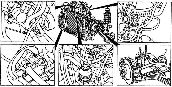
Pic. 5.4. Removal and installation of the engine with transmission:
1. Left half shaft,
2. Cooling system radiator,
3. Compressed air intercooler,
4. Bolt,
5. Power steering pump,
6. Collar,
7. Power steering reservoir,
8. Support bracket,
9. Right eye,
10. Left eye.
3. Remove the cooler 2. Compressed air intercooler (intercooler) 3 attached to radiator 2.
4. Remove the alternator drive belt.
5. Turn off bolts 4 fastenings of the pump of the amplifier of a steering to a cover of a timing chain.
6. Remove clamp 6 fastening power steering reservoir 7 to bracket 8.
7. Attach the lift to the eyes 9 and 10.
8. Remove the engine from the subframe.
Installation
9. Installation is made in an order, the return to removal.