



- disconnect the negative terminal from the battery;
- in the car cabin, lift the protective cover of the gear shift lever, unscrew the lever at the bottom and remove it together with the cover;
- lift the front of the car with a jack and place it on supports;
- drain transmission oil (see below);
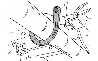
Figure 186. Cardan shaft safety bracket
- unscrew the safety bracket for fastening the cardan shaft, shown in the figure 186;
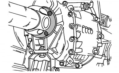
Figure 187. Fastening the cardan shaft to the gearbox
- disconnect the cardan shaft from the gearbox. When unscrewing the nuts with the head, hold the bolt heads with a spanner. The shaft can be rotated to access all bolts. The cardan shaft mount is shown in the figure 187;
- unscrew the intermediate support of the cardan shaft, as well as the nearby fastenings of the parking brake cable. Pull out the cardan shaft and hang it on a wire loop from the bottom of the car in a suitable place. The cardan shaft should never be left untied;
- insert a wooden block (size 90x20x30 mm) between the engine casing and the cross beam to prevent the engine from moving off the supports when the gearbox is removed;
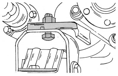
Figure 188. Fastening the box support in the center of the crossbar
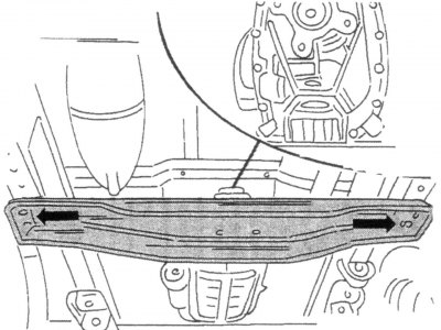
Figure 189. Fastening the rear crossmember of the gearbox to the side members
- remove the rear engine crossmember by first unscrewing the connection shown in the figure 188, and then shown by arrows in the figure 189 crossmember mounting bolts;
- unscrew the clutch slave cylinder from the gearbox without removing the hydraulic hoses. Remove the gasket installed between the cylinder and the gearbox;
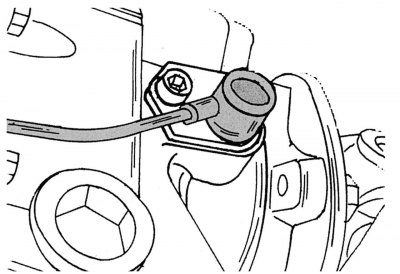
Figure 190. Speedometer pulse sensor connector
- disconnect all electrical wires leading to the gearbox, as well as the plugs for the reverse signal switch and the speedometer sensor. The fastening of the latter is shown in the figure 190. To remove, unscrew the internal hex bolt;
- place a jack under the gearbox. It must be of suitable height. You can put a wooden block on the jack lift rod to support the gearbox. Raise the gearbox with a jack and unscrew the mounting bolts between the engine and the gearbox. Also disconnect the "ground" wire;
- carefully pull the gearbox back and then lower the jack. When doing this, make sure that the clutch shaft comes out of the splines of the driven disk to avoid deformation of the shaft or damage to the disk.
Warning! Always perform the work with an assistant - he must hold the gearbox when lowering the jack. Caution: Possibility of injury!
Before reinstalling the gearbox, it is necessary to check the condition of the clutch: how much mileage it has covered, whether it worked properly, etc.
The gearbox must be installed in the reverse order, taking into account the following instructions:
- apply a little plastic grease to the splines of the clutch drive shaft;
- raise the gearbox with a jack and insert the shaft into the hole in the driven disk hub. If necessary, turn the shaft flange slightly. Move the box towards the engine. The mounting bushings on the engine must fit neatly into the holes in the gearbox housing;
- bolt the gearbox housing to the engine with a torque of 55 Nm. Tighten the "mass" wire with the same torque;
- install the crossmember, "tighten" the gearbox support mounting bolt in the middle and tighten the bolts on both sides of the crossmember to 45 N·m. Tighten the support mounting bolt and nut to 90 N·m. Remove the wooden block;
- insert the speedometer pulse sensor plug and tighten the mounting bolt to 8 Nm (see figure 190);
- insert the reverse signal plug;
- install the slave cylinder with the gasket and evenly tighten the two mounting bolts to a torque of 25 N·m;
- install the cardan shaft on the gearbox flange, tighten the bolts evenly in a circle to a torque of 60–65 N·m;
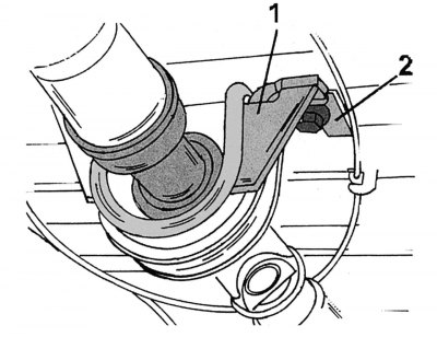
Figure 191. Fastening the intermediate support of the cardan shaft: 1 - safety bracket; 2 - Parking brake cable holder
- install the intermediate support of the cardan shaft (figure 191). Install parts 1 and 2 accordingly and tighten the bolts to a torque of 85–90 N·m. Tighten the bolts securing the driveshaft safety bracket to the same torque (see figure 186);
- apply high-temperature plastic grease to the gear shift lever seat cone and secure it in the shift mechanism. Tighten the bolt to 65 Nm. Put on the lever protective cover and secure it;
- connect the negative terminal of the battery;
- fill in transmission oil. If it has not drained, check its level and, if necessary, bring it up to normal;
- if the radio has a security code, enter the code and set the time.