
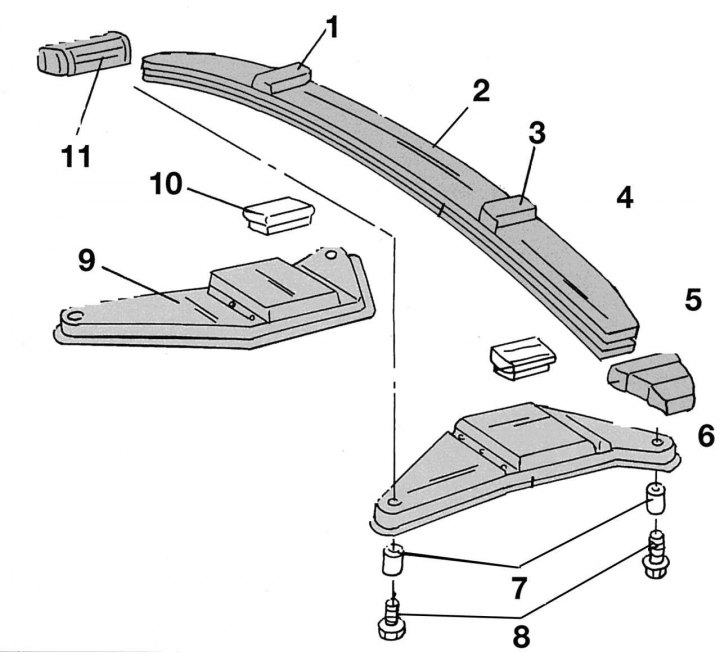
Pic. 242. Front spring mounting details: 1 - top rubber pad; 2 - spring; 3 - top rubber pad; 4 - bottom rubber pad; 5 - rubber tip; 6 - mounting bracket; 7 - sleeve; 8 - bolt, M12x1.5; 9 - mounting bracket; 10 - bottom rubber pad; 11 - rubber tip
On fig. 242 shows the mounting of the front spring. Before starting work, prepare a solid wooden beam corresponding to the length of the spring. In addition, you will need a ball stud puller to release the tie rod joint, a rolling trolley jack, and a hydraulic jack. When removing the spring, proceed as follows:
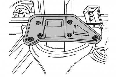
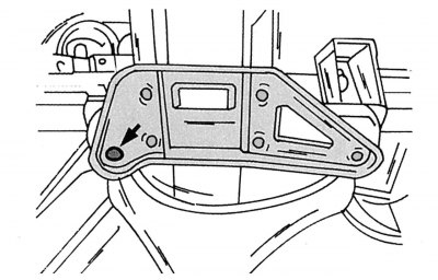
Pic. 243. Front spring mounting bracket fastening
- jack up the front of the vehicle and remove two of the six mounting bracket bolts on both sides as shown in fig. 243. After that, lower the car back on the wheels;
Note. If you do not unscrew the bolts in the specified order, then they will not be able to be removed.
- remove the caps and unscrew the wheel bolts;
- raise the car in front and place it on supports, as shown earlier;
- remove the wheel;
- remove the brake caliper and tie it with wire so that it does not hang on the brake hose;
- disconnect the tie rod end from the steering knuckle arm;
- install rolling (hydraulic) jack under the control arm and raise it by about 10 mm;
- unscrew the shock absorber from the steering knuckle as described earlier. Lower the transverse lever again;
- unscrew the top bracket (three bolts). If a stabilizer bar is installed, remove the bracket with the stabilizer fixed to it and lift it up;
- unscrew and knock out the bolts securing the transverse lever from the rear side. Do the same with the front mount, then remove the transverse lever;
- place a jack under the middle of the front spring. A hydraulic jack is best suited for this;
- from the underside, unscrew the remaining four central bolts on both mounting brackets 6 and 9 (see fig. 242), lower the jack slowly. The assistant should hold the spring on one side. Then remove the removed spring in any direction.
When installing the front spring, the following operations must be performed:
- mark the center of the spring and front axle with a felt-tip pen;
Pic. 244. Correct installation of the upper rubber spring cushion
- stick the upper rubber pads 1 and 3 with holders on the spring and insert them into the openings of the carrier beam. When installing, pay attention to the correct installation and colors of the cushions. Black is installed on the driver's side, red - on the front passenger side. On fig. 244 shows that cushions should be placed smooth side down (indicated by an arrow);
- rubber pads put on the ends of the spring 1 and 3 (see fig. 242) lubricate with oil and insert until it stops on both sides. The beveled side of the pads should be facing up;
- insert the ends of the spring with rubber pads into the holes of the transverse levers. In this case, the center lines marked with a felt-tip pen on the spring and the axle beam must match. To make the rubber tips easier to insert, they can be lubricated with Vaseline (oil can damage tires!);
Pic. 245. Installing the front spring (until the stop of the upper pillows)
- put a wooden beam on a jack so that both ends of it touch the ends of the spring (pic. 245), and raise the jack until the top cushions rest;
- place the rolling jack under the transverse arm, set it in the desired position and insert its front rod into the eye. Install the bolt from the inside and secure with a nut and washer. Tighten the nut by hand. After that, lower the jack;
- pull the lever back and insert its second rod into the eye. Align the holes, insert the bolt and tighten the nut with the washer;
- install the upper suspension bracket and tighten the bolts to a torque of 40-50 Nm;
- bring the shock absorber strut to the steering knuckle and tighten the four mounting bolts with a torque of 300-320 Nm;
- attach the steering rod, tighten the nut with a torque of 120-130 Nm;
- install the brake caliper. Tighten the bolts to 175-205 Nm;
- install the wheels, tighten the bolts to a torque of 160-180 Nm. Typically, the described work is carried out on a lift or a viewing ditch. Otherwise, the working space during these operations will be severely limited;
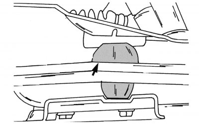
Pic. 246 Installing the Mounting Bracket and Bottom Cushion (Tighten the bolt with the bushing indicated by the arrow by hand)
- install mounting brackets 6 and 9 (see fig. 242) and lower rubber pads 4 and 10, then screw in the place shown in fig. 246. Sleeve 7 (see fig. 242) must go into the hole. At the same time, pay attention that the flat trim is installed on the driver's side, the higher one on the passenger side;
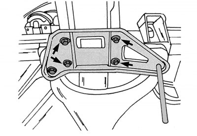
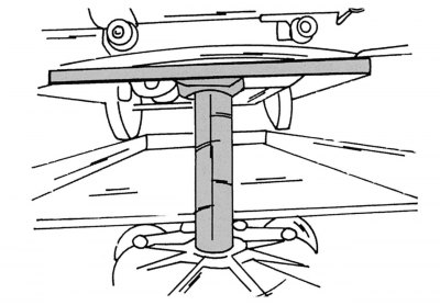
Pic. 247. Final installation of the mounting bracket
- tighten the four central bolts in turn (pic. 247) and screw by hand in a circle, without tightening to the end. Indicated by an arrow in Fig. 246 tighten the bolt to a torque of 140–160 Nm;
- insert a suitable rod into the mounting bracket (see fig. 247) and align its hole with the top thread (do not install bushing yet). Tighten the four central bolts to 65-75 Nm;
- remove the rod, insert a bolt with a bushing and tighten with a torque of 140-160 Nm;
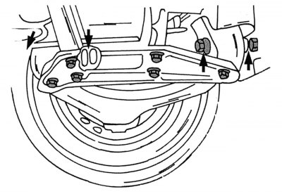
Pic. 248. Mounting the transverse arm
- roll the car about 1 m forward, then back, shake it several times. Tighten the fastenings of the transverse arm in the places shown in fig. 248, torque 130-150 Nm;
- several times to press a brake pedal to satisfactory pressure in system.