
Remove gear shift cover (section 10.2.2).
Remove front and rear gearbox covers (chapter 10.2.3 or 10.2.4).
Remove reverse gears (section 10.2.5).
Remove the shift forks.
Get off the leash (1) pin (3) on the reverse gear fork shaft and move the leash as far forward as possible (see fig. 183).
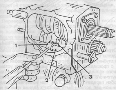
Pic. 183. Removing the stem with the reverse gear fork.
1 - leash for reverse gear engagement,
2 - rod with reverse gear engagement fork,
3 - pin.
Remove the rod with the fork from the gearbox housing and at the same time remove the leash.
Using a socket wrench, loosen the nut securing the intermediate shaft and unscrew it (see fig. 184). To prevent shaft rotation, engage two gears at the same time.
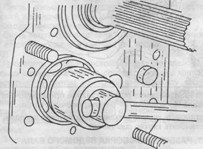
Pic. 184. Unscrewing the nut of the intermediate shaft.
Loosen the bearing cap screws (1) and remove the cover together with the adjusting ring (see fig. 185).
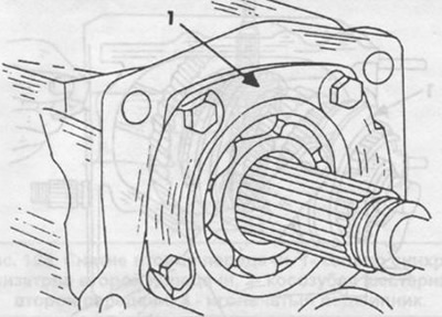
Pic. 185. Removing the bearing cap (1) in the gearbox.
Remove the locating groove bearings from the front and rear ends of the intermediate shaft using a puller as shown in fig. 186.
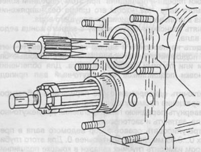
Pic. 186. Removing the front intermediate shaft bearing.
Remove the grooved bearing from the rear end of the output shaft.
Put a technological sleeve on the rear end of the driven shaft, which prevents the first gear from moving, and tighten the flange fastening nut.
Move the driven shaft back in the gearbox housing and remove the drive shaft assembly forward. Pay attention to the position of the fourth gear synchronizer at the free end of the input shaft and the needle bearing of the front input shaft support.
Clutch (1) put the third and fourth gears in the third gear engagement position. Move the driven shaft back to the stop and remove it obliquely upwards from the gearbox housing (see fig. 187).
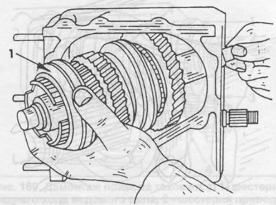
Pic. 187. Removing the driven shaft.
Similarly, remove the intermediate shaft from the crankcase.
To install the gear, do the following:
Install the intermediate shaft into the gearbox housing.
Put a technological sleeve on the rear end of the driven shaft and secure with a flange fastening nut.
Set the 3rd and 4th gear clutch to the 3rd gear position.
Tilt back the driven shaft to install it in the crankcase.
Insert the needle bearing into the drive shaft.
Put the fourth gear synchronizer ring on the cone of the drive shaft gear.
Install the input shaft assembly from the front into the gearbox housing, while lifting the front end of the output shaft so that its trunnion enters the input shaft needle bearing without tension.
Remove the service sleeve from the rear end of the driven shaft.
Fit the front and rear ends of the intermediate shaft with locking groove bearings using a mandrel or light hammer blows. Raise the intermediate shaft to facilitate installation of the bearings.
Engage two gears at the same time and block the rotation of the intermediate shaft.
Screw in the front nut securing the intermediate shaft, tighten and lock.
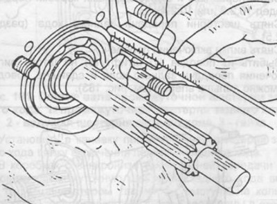
Adjust the axial clearance of the driven shaft within 0... 0.05 mm, preferably 0. To do this, use a depth gauge to measure the depth of the groove in the bearing cap and the distance from the end of the adjusting ring on the outer ring of the bearing to the split surface of the gearbox housing.
Pic. 188. Measurement of the axial clearance of the driven shaft.
Install the selected adjusting ring in the bearing cover, put the cover on the bearing and secure.
Set reverse gear.
Install and secure the gearbox rear cover.
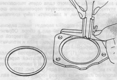
Adjust the axial clearance of the drive shaft within 0... 0.05 mm, preferably 0. To do this, use a depth gauge to measure the depth of the groove in the front cover of the gearbox with the gasket and the distance between the end face of the setting ring on the outer ring of the drive shaft bearing and the split surface of the gearbox housing (see fig. 189). Spare parts come with adjusting rings with a thickness of 0.1; 0.2 and 0.3 mm.
Pic. 189. Measurement of the axial clearance of the drive shaft.
Adjust the axial clearance of the intermediate shaft within 0.07... 0.15 mm. To do this, use a depth gauge to measure the depth of the groove in the front cover of the gearbox with the gasket and the distance between the end face of the adjusting ring on the outer ring of the intermediate shaft bearing and the split surface of the gearbox housing (see fig. 190), when measuring, the intermediate shaft must be pressed against the rear cover of the gearbox. Install the selected adjusting ring in the front cover of the gearbox, put the cover on the gearbox housing, wrap and secure the mounting bolts.
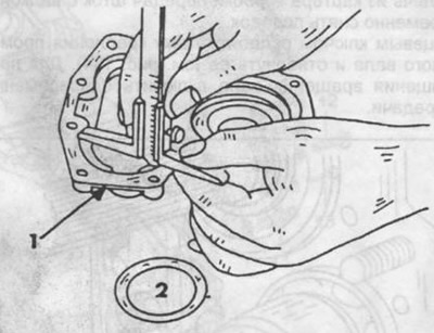
Pic. 190. Measurement of the axial clearance of the intermediate shaft.
1 - cover,
2- adjusting ring.
Install the gear shift cover.
Install the clutch housing.