
Intermediate shaft
In gearboxes for eight-cylinder engines up to number 544, a bearing with a collar on the outer ring was installed on the front end of the intermediate shaft. When removing the intermediate shaft, this bearing can not be removed from the shaft. Dismantling works are carried out in the following sequence:
Remove the intermediate shaft rear bearing with the groove on the outer ring.
Unscrew the fastening nut on the rear end of the driven shaft.
Loosen the nut on the drive shaft.
Remove bearings from drive and driven shafts.
Raise the input and output shafts and slide the intermediate shaft back until the front bearing comes out of the hole in the gearbox housing.
Pull the input shaft forward from the crankcase, taking into account the position of the fourth gear synchronizer ring and the needle bearing between the input and output shafts.
Set the 3rd and 4th gear clutch to the 3rd gear position.
Move the output shaft to the right and remove it obliquely upwards from the gearbox housing (see fig. 187).
Similarly, remove the intermediate shaft together with the bearing from the gearbox housing. When overhauling, the bearing with a collar on the outer ring can be replaced with a bearing with a groove on the outer ring, after which the drive shaft can be installed with the bearing as described above. The rest of the assembly work is carried out as described for later production gearboxes.
Synchronizer
On gearboxes of early releases, cylindrical coil springs are installed in the synchronizers. The design of such a synchronizer is shown in Fig. 202. To disassemble the synchronizer sleeve, wrap it with a rag and pull it out of the hub along with the leashes. Check for wear on all parts. When assembling, install the springs and leashes in the synchronizer hub and push on the synchronizer sleeve.
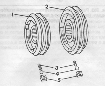
Pic. 202. Details of the synchronizer with cylindrical twisted springs.
1 - synchronizer 3/4 gears,
2 - synchronizer 1/2 gears,
3 - spring,
4 - ball,
5 - leash.
If you press the leash in front (5) in fig. 202, the ball will move and return to its original position. For distinction, a chamfer is made on the leashes of the 1/2 gear synchronizer. When installing the leashes, the chamfer should be directed towards the second gear.
The 1/2 gear synchronizer must be assembled so that the narrow part of the hub and the shoulder on the synchronizer sleeve (arrows in fig. 203) were put into first gear.
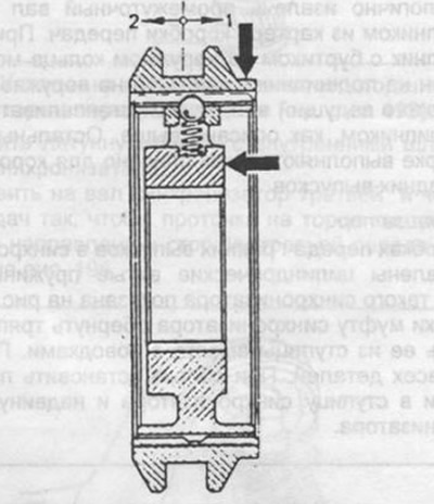
Pic. 203. Section of the synchronizer of the first and second gears, (coil spring synchronizer).
The 3/4 gear synchronizer must be assembled so that the wide part of the hub and the groove on the synchronizer sleeve (arrows in fig. 204) were on the same side.
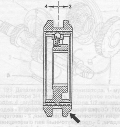
Pic. 204. Section of the synchronizer of the third and fourth gears (coil spring synchronizer).
Checking the level and changing the oil in a manual transmission
To check the oil level, unscrew the plug on the side of the gearbox and lower your index finger into the hole. If your fingertip touches the surface of the oil, the level is normal.
Oil change is done on a warm gearbox (but not hot). Unscrew the plug on the underside of the gearbox, substitute a container and drain the oil.