
Loosen the mounting bolt and remove the reverse gear lever ("2" in fig. 171).
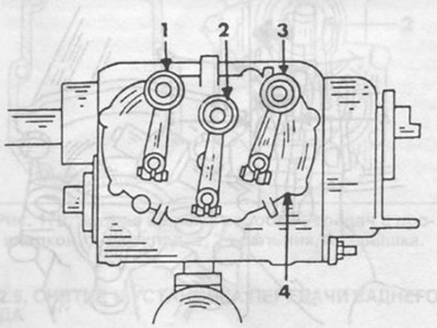
Pic. 171. Gear shift cover with shift levers.
1 - 3/4 gear off lever,
2 - reverse gear engagement lever,
3 - 1/2 gear engagement lever,
4 - gear shift cover.
Remove the set ring from the reverse gear shaft.
Loosen the gearshift cover bolts.
Carefully remove the cover from the dowel pins and, at the same time, with hammer blows, shift the reverse gear engagement shaft towards the crankcase, move the cover away from the split surface of the crankcase to a distance at which you can put the palm of your hand into the slot (see fig. 172 and 173).
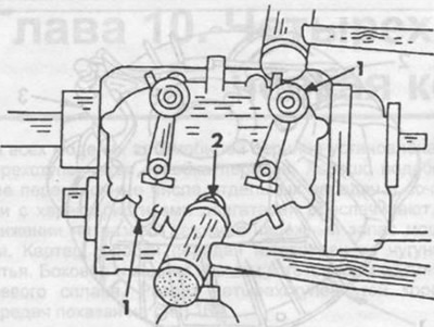
Pic. 172. Reverse gear engagement shaft.
1 - locating pin,
2 - reverse gear engagement shaft.
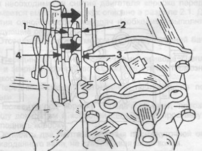
Pic. 173. Removing the gear cover.
1 - 3/4 gear engagement rod,
2 - 3/4 gear engagement fork,
3 - fork of inclusion of 1/2 transfers,
4 - 1/2 gear engagement rod.
Remove the forks 2 and 3 from the switching rods in the direction indicated by the arrows in fig. 173.
Tilt the cover of the switching mechanism down, then lift it up.
When installing the gear selector cover, perform the following work:
Glue a new gasket onto the thoroughly cleaned detachable surface of the gearbox housing with grease.
Set the reverse gear fork rod leash to the middle position.
Install the cover of the mechanism of inclusion so that the pin of the shaft of inclusion of the reverse gear entered into the groove of the leash.
Press the cover against the crankcase so that the forks are simultaneously put on the corresponding gear shift rods.
With light blows of a hammer, place the cover on the split surface of the gearbox housing. When doing this, pay attention to the correct fit of the cover on the dowel pins. Pull the reverse gear engagement shaft out of the cover.
Screw in the mounting bolts and tighten evenly in a diagonal pattern.
To properly install the cover of the gear shift mechanism, it is necessary to move the shaft and the reverse gear engagement finger relative to the cover ("3" in fig. 174) so that a certain distance is maintained between the pin and the split surface of the cover (distance "V" in fig. 174).
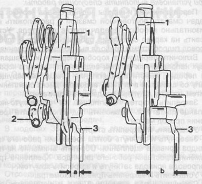
Pic. 174. Adjusting the position of the reverse gear engagement finger.
a=10 mm, the distance between the split surface and the pin after the cover has been installed.
h= 25 mm, distance between the split surface and the pin before fitting the cover,
1 - gear shift cover,
2 - reverse gear engagement lever,
3 - a finger with a reverse gear engagement shaft.
Put a washer on the reverse gear engagement shaft.
Install the adjusting ring into the groove on the reverse gear shaft.
Install the reverse gear lever on the shaft splines and tighten the lever mounting bolt.
Check the operation of the mechanism by successively engaging all gears.
Pour oil into the gearbox.