



Secure the driven shaft by the flange in a vice.
Loosen the nut on the front end of the shaft (see fig. 191).
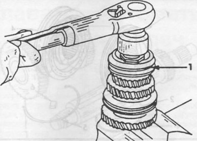
Fig. 191. Unscrewing the driven shaft nut.
1 - synchronizer clutch.
Remove the third and fourth gear synchronizer, the internal spline washer, the third gear helical gear and the needle bearing in sequence.
Turn the driven shaft over and secure it in a vice by the seat of the needle bearing. To avoid damaging the shaft surface, place soft metal jaws in the vice.
Remove the washer, first gear helical gear and needle bearing (see fig. 192).
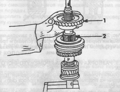
Fig. 192. Driven shaft with helical gear of first gear and needle bearing.
Remove the first gear needle bearing ring and then remove the washer, synchronizer ring, synchronizer and washer.
Remove the helical gear with the second gear synchronizer ring and the needle bearing (see fig. 193).
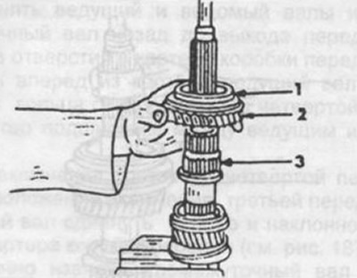
Fig. 193. Removing second gear.
1 - second gear synchronizer ring,
2 - helical gear of the second gear,
3 - needle bearing.
Check the wear and condition of all parts. Place the synchronizer ring on the corresponding cones on the gears and measure the gap between the ends of the gears and rings with a feeler gauge, as shown in Fig. 194. If the gap is less than 0.5 mm, it is necessary to replace the synchronizer ring or (in case of high wear) gear.
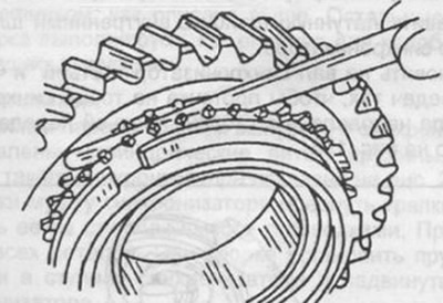
Fig. 194. Checking the wear of the synchronizer rings.
When assembling the driven shaft, perform the following work:
Secure the driven shaft in a vice using aluminum jaws as shown in Fig. 195.
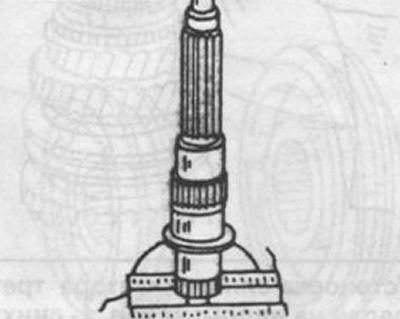
Fig. 195. Fastening the driven shaft for assembly.
Lubricate and install the needle bearing, second gear helical gear with synchronizer ring and washer on the driven shaft.
Install the synchronizer of the first and second gears so that the flange on the coupling is directed towards the first gear pinion (arrow in Fig. 196).
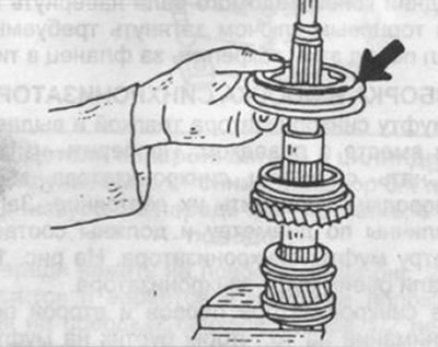
Fig. 196. Installing the first and second gear synchronizer clutch.
Install the synchronizer ring and washer.
Install the driven shaft on a solid base, heat the first gear pinion needle bearing ring and, using a piece of pipe of the appropriate diameter, press the ring onto the shaft (see fig. 197).
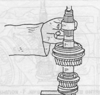
Fig. 197. Installing the first gear pinion needle bearing ring (see fig. 198).
Install a washer on the first gear pinion.
Install the process sleeve on the driven shaft and tighten the fastening nut by hand.
Turn the driven shaft over and secure the process sleeve in a vice.
Lubricate and install the needle bearing and helical gear onto the shaft.
Install the brass washer with internal splines and the synchronizer ring.
Install the third and fourth gear synchronizer on the shaft so that the groove on the end of the synchronizer is directed towards third gear, as shown in Fig. 198.
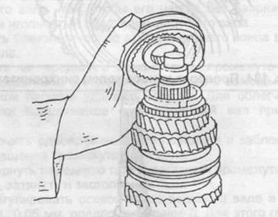
Fig. 198. Installing the synchronizer of the third and fourth gears on the driven shaft.
1 - synchronizer,
2 - synchronizer ring.
Screw a flange nut onto the front end of the driven shaft and tighten it with a socket wrench to the required torque. Before doing this, secure the shaft by the flange in a vice.