
Install a new oil seal in the cylinder block. Using a hammer handle, firmly insert the oil seal into the groove (see fig. 74). To ensure the necessary overlap, cut the gland above the split surface (see fig. 75). The height of the protrusion of the gland ends depends on the color of the gland material. For a graphite gray gland, the protrusion is 1.0 mm, for a yellow-brown - 0.5 mm.
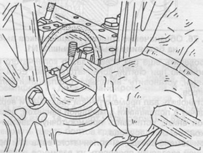
Pic. 74. Installation of the gland using the handle of the hammer.
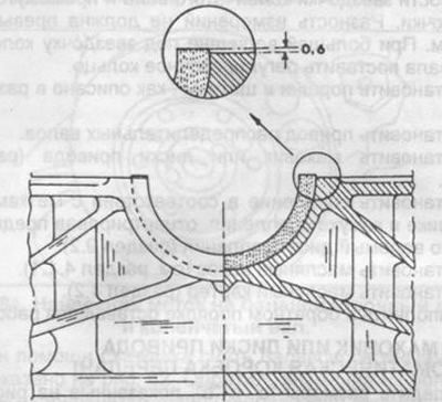
Pic. 75. Overlap after cutting the gland.
Carefully install the crankshaft into the cylinder block. If the pistons were in the cylinder block, then insert the lower connecting rod heads onto the crankshaft journals.
Place the bearing shells in the main bearing caps and lubricate their surface.
Install the covers in the cylinder block with a hammer with a rubber or plastic head and press into place. Lids can only be placed in one position. Check the label on the cover. On fig. 76 shows the location of the symbols on the main bearing cap.
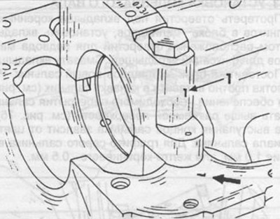
Pic. 76. The designation of the bearing cover is stamped on the side of the cover. Cover #1.
Tighten the main bearing cap bolts evenly to 80 Nm.
Rotate the crankshaft to clear the jam. With increased resistance to rotation, remove it with a light blow of a hammer with a plastic head on the bearing caps.
Check the crankshaft end play again as described when removing the crankshaft. If the clearance is increased, install bearings with larger flanges.
Install the intermediate sprocket shaft and upper sprocket in bearings with the oil groove at the bottom, install the intermediate sprocket and drive chain guide.
When replacing the crankshaft sprocket or intermediate sprocket, check their relative position. To do this, it is necessary to measure the distance from the end surface of the cylinder block to the end surface of the crankshaft sprocket and the intermediate sprocket. The measurement difference should not exceed 0.1 mm. With a larger value, place an adjusting ring under the crankshaft sprocket.
Install pistons and connecting rods as described in section 3.4.5.
Install the camshaft drive.
Install flywheel or drive discs (section 3.6.4).
Install the clutch in accordance with the marks on the flywheel and clutch cover, having centered the clutch disc beforehand (section 9.2).
Install oil pump (see section 4.1.1).
Install oil sump (section 4.2).
Carry out the rest of the work in reverse order.